


General
1. What training materials are available for UniLogic™?
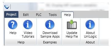
Once you download UniLogic, you can access a lot of training material from within the software. Click the Help tab on the UniLogic ribbon to access it the following:
1. Help: Click this to open the UniLogic Help file. You can also press F1 to open it.
2. Tutorial Videos: If you are connected to the Internet, this opens the Unitronics YouTube channel, which offers a broad variety of instructional videos.
3. Download Sample Apps: This downloads a folder containing many sample applications. You can learn from them–or tweak them to suit your project.
2. Electromagnetic noise--how can I protect my application?
Following specific guidelines when you build and wire your system can help. Guidelines are in this document: “System Wiring Guidelines”
3. SD cards- Must I format an SD card in order to use it with UniStream?
Yes, you must format the SD card to FAT 32. You can format the SD card in Windows by navigating to Computer, right-clicking on the SD card drive, and selecting Format.
Hardware Activation
What is Unitronics Hardware Activation?
For more information please click here >>>
Software
1. What are the minimum system requirements to install UniLogic?
Minimum System Requirements
- 1.6 GHz or faster processor
- 1 GB of RAM
- 10 GB of available hard disk space
- 5400 RPM hard drive
- DirectX 9-capable video card running at 1024 x 768 or higher display resolution
- 32-bit colors
Minimum requirements: Windows XP (SP3) and above.
Recommended requirements: Vista (SP2) and above. Note that all Windows versions must be installed with the latest service patches released by Microsoft. Both x86/x64 systems are supported.
Notes:
-Windows XP: the UniLogic installation will also include SQL 2008 R2 Express.
-The UniLogic installation files for higher versions of Windows do not require SQL 2008 R2 Express.
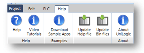
2. Where can I find the latest Bin files and Help files for UniStream and UniLogic?
The Help tab contains options for updating BIN and Help files
3. How can I update UniStream Bin files?
This firmware can be updated via a USB drive (DOK) containing updated UniStream files. The files can be updated and downloaded using UniLogic, then installed on the UniStream panel through UniApps.
These features are under the UniStream Management drop-down menu in the PLC tab on the UniLogic ribbon.
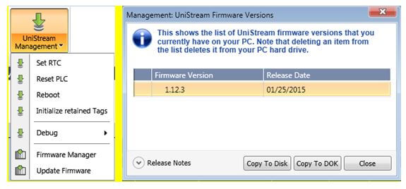
The most recent firmware can be downloaded online by selecting Update Firmware. Next, copy the files to a USB drive by selecting Firmware Manager, selecting the desired firmware version, then selecting Copy to DOK (Disk on Key).
Next, insert the USB drive into a USB port on the UniStream panel.
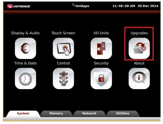
Open UniApps and then select Upgrades.
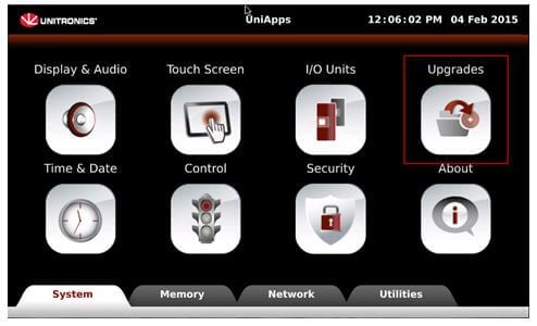
Select the option Upgrade PLC to start the firmware update process.
**Note ** The process may take 10-20 minutes, and the system will automatically reboot.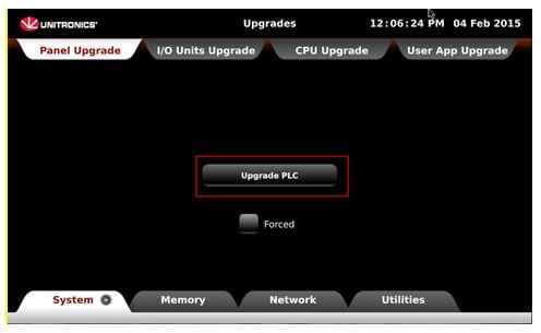
Notes:
-Do not turn off the power to the system during the upgrade process.
-It is recommended to select the Forced option.
Communications
1. I’m using Windows 8 and I’m having trouble with the USB drivers to connect to the UniStream PLC, how can I solve this?
Please note that you must enable Win8 to support unsigned USB drivers.
Step-by-step guide: enabling unsigned drivers (USB) on Windows V8.1.
- Move your mouse cursor to the upper right of the screen
- Select settings ->Change PC settings->Updates and Recovery > Recovery > Under “Advanced Startup” > Restart now.
Now the system will restart; it may take several minutes to open the Boot menu. - Select Troubleshoot from the Boot menu
- From the next menu, select Advanced Options
- From the next menu, select Windows Startup settings,
then Click Restart. - The computer will restart and the Boot menu will appear.
- Choose Disable Driver signature Enforcement from the menu by using your keyboard numbers.
Windows will start.
You can now install unsigned drivers.
2. What communications ports does the PLC have and what protocols are supported?
There are communication ports on both UniStream HMI panels and CPUs.
UniStream HMI panels comprise:
- 2 Ethernet ports, RJ-45, 10/100MHz
- 2 Type A, USB ports, high speed
- 1 Type mini B USB port, high speed
Note that the Panel has its own IP address
UniStream CPUs comprise:
- RS 485
Note that the settings for the serial port allow you to enable MODBUS communications.
- CANbus
Note that the CPU also has its own IP address.
You can also add COM modules, available by separate order, to your Hardware Configuration.
- UAC-01RS2: one RS232 COM port.
- UAC-02RS2: two RS232 COM ports.
- UAC-02RSC: one RS232 and one RS485 COM port.
This is a partial list of the communications protocols are supported by UniStream PLCs. To see the full list, look within UniLogic itself, or check the UniLogic Help file:
- MODBUS RTU
- MODBUS TCP/IP
- CANOpen
- CANLayer 2
- UniCAN –Unitronics proprietary CANBus protocol
- FTP Server and Client
- SNMP V1/V2/V2c/V3
- Ethernet/IP
Third-party Protocols
You can use the Message Composer and the Third-party Protocol Ladder functions to communicate with virtually any external device, such as bar-code readers and printers
Use TCP Server /client in conjunction with the Message Composer for applications that require a proprietary Ethernet communication protocol.
Do not use this feature with built-in communication protocols offer by UniStream such as MODBUS.
You can set up to four (4) TCP Servers. TCP Server is dynamic in nature. Each Server can handle up to 16 simultaneous connections.
You can also configure the UniStream PLC as TCP client. When you add a TCP Client, UniLogic automatically creates a supporting Global operand struct.
The CPU Ethernet support up to 32 TCP server/clients and UDP sockets.
X: number of TCP servers; Y: number of TCP clients; Z: number of UDP sockets
X: <= 4
X + Y + Z <= 32
3. What is the difference between the CPU and the Panel IP address?
The CPU IP is used for communicating using raw protocol (TCP TX & TCP RX utilities). For example, a barcode scanner connected to UniStream via Ethernet. The Panel IP is generally used for downloading applications, viewing via VNC and online Test mode, and sending SMS or email.
4. How do I remotely access UniStream via VNC viewer?
You can access UniStream using a VNC viewer from a computer, phone, or tablet with an Ethernet or mobile connection. When connecting via VNC over a local network, make sure to connect to the Panel IP and port 5900. You can have many connections at the same time to the same PLC.
You can assign different levels of connection to the VNC users:
- View only: The user will only be able to view the PLC but not control it on the VNC viewer.
- Full access: The User will have full access to the PLC remotely via the VNC viewer
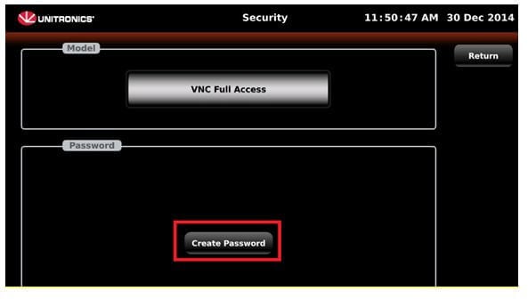
Setting Levels
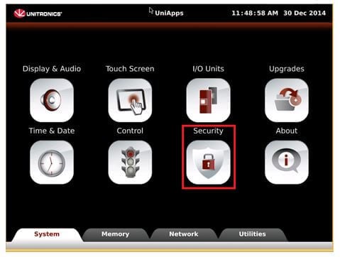
1. Open UniApps and press on the Security icon.
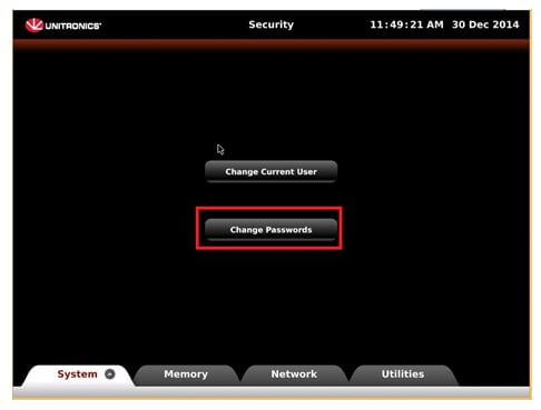
2. Select the option Change password.
3. Click on the model option and select the desire function.
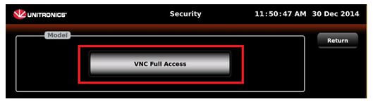
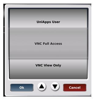
4. Select Create password and write the desired password.
5. How many Ethernet connections can I have connected to a UniStream at one time?
Since UniStream is run by Linux, sockets are virtual; many dozens of virtual sockets are available.
6. Where and how many COM modules can I connect to a single UniStream?
All COM modules must be connected directly to the CPU or to another COM module. You cannot place a COM module after an I/O module, or after a Short-Range Local I/O Expansion Kit. The maximum number of COM modules that can be placed on a UniStream panel is 4.
7. What modems are supported by the UniStream PLC?
The modems supported by the UniStream PLC are:
- Enfora GSM1308-50
- Cinterion TC65
- Cinterion: MC55i
- Cinterion BGS2T
Please note that Cinterion will be discontinuing the MC55i and it will be replace by the BGS2T
8. How do I set up a modem, and what hardware will I need?
You can connect a modem via the Panel USB Host port, or via a UniCom module with a RS232 port.
Configuring ports
– Panel USB port: connect the modem to the USB port via a USB to serial converter. The supporting UniStream driver is PL2303, which is compatible with most USB to Serial converters.
In the Solution Explorer, click PLC Communication > Physical >Panel USB Port to open the Properties Window, and then select Enable USB for Serial Device. Next, open the Panel USB Port Settings, click the Initialize Port for: options and then select Modem.
(Vision users: please note that no ‘Prepare PLC-side modem’ procedure is required.)
– RS232 module (ex. UAC-01RS2):
Include the UniCom module in your Hardware Configuration: in the Solution Explorer, click Hardware Configuration> Local I/O and COM Modules and add the COM module.
Then, in the Properties Window, open Com Port Settings> Initialize Port for: Options and select Modem
To link a port to the modem: click Solution Explorer > Modems, and click Communication Channel. A drop-down list will display the available ports; click one to select it.
9. Is UniStream EtherNet/IP™ compliant?
Yes, Unitronics UniStream has passed the ODVA conformance testing and received a Declaration of Conformity (DOC).
10. What type of EtherNet/IP functionality does UniStream support?
Typically, an EtherNet/IP™ device behaves either as an I/O Adapter or an I/O Scanner.
However UniStream is a unique EtherNet/IP™ supporting device as it supports both functionalities.
This means that a single UniStream controller can function as both an:
- EtherNet/IP I/O Adapter
As an adapter, UniStream is a target, accessible to any Ethernet IP scanner device. The programmer determines which data may be accessed by a scanner. - EtherNet/IP I/O Scanner
As a scanner, UniStream can initiate an EtherNet/IP session, and can read and write data to Adapters. Note that multicast is supported.
Is UniStream EtherNet/IP™ compliant?
Yes, Unitronics UniStream has passed the ODVA conformance testing and received a Declaration of Conformity (DOC).
11. How do I enable UniStream to communicate via EtherNet/IP?
In UniLogic, communications are a simple configuration task. No programming is required.
A single controller can contain multiple node definitions for both Scanner and Adapter, as shown in the following figure.
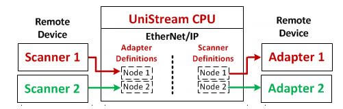
However, note that as defined in the EtherNet/IP™ protocol, a scanner can connect to only one adapter at a time.
The sessions run according to the parameters that you configure in the node properties.
12. Can I use the USB port on the UniStream panel to connect with serial devices?
Yes. You can use the USB port for either modem or other device, by selecting it via the parameter USB Port Settings> Initialize Port for> Tx/Rx
13. Can the two Ethernet ports on the Panel act as a switch? (Bridging)
Yes, the ports act as a pass through or switch connection. This allows you to connect to any controller within a network configured as daisy-chain or cascading network.
14. Does the UniStream have Web Server capabilities?
Yes, UniStream can act as a Web Server. Users can access Web pages hosted by UniStream using any web browser. You design web pages using UniLogic’s built-in Web Page Editor. No HTML coding required–you simply drag&drop elements and widgets, similar to the HMI Displays Editor.
You can also create different user accounts and multi-level password settings, and apply them to individual web pages.
Additional information can be found within the UniLogic Help file under Communications/ Web Server.
15. Does the UniStream support SSL encryption for email, such as Gmail?
Yes, UniStream supports SSL encryption email servers. By default, Gmail, Hotmail, and Yahoo are supported. Additionally, you can use a custom server by entering the server address and port.
Note: A DNS Server must be entered under the Panel Ethernet configuration for the controller to reach the mail server.
Logic, HMI & application
1. What is the maximum of HMI screens you can create?
You can create up to 256 screens. Each screen can contain up to 256 objects.
2. Can I import/export my project to/ from UniStream PLC?
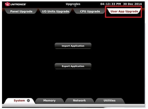
To Import/Export applications, navigate in UniApps to the Upgrades menu, then select the User Application Upgrade tab.
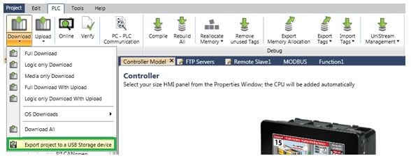
You can also install USB flash drive with the application, and import it into UniStream via UniLogic. This is done by opening the PLC tab on the ribbon and selecting Export project to a USB storage device, located on the Download menu.
Please note:
- Only one project can be saved to the USB flash drive at a time.
- This tool is not meant to export the application to be read by the UniLogic PC.
3. What are actions?
You use Actions to program event-driven events. There are two classes of Actions:
- Project-level Actions
- HMI Element Actions
Project-level Actions enable you to use events to drive actions such as Load Screen, or to play Sounds.
To create an action:
- Select Actions from the Solution Explorer tree.
- Click Add New Action.
- Define the Event Name, select an Event Trigger and the resultant Action.
Please Note
- The Event Trigger must be linked to a Set Coil.
- The coil is automatically reset by the OS after the Action is executed.
If the Action requires you to select an entity, such as a screen or sound file, make your selection in the Properties window.
HMI element Actions enables a single Touch Element to trigger multiple events. Multiple bits can be linked to one element, triggering Load screen, set, reset, and toggle bits, and more.
Note:
The following elements do not have the Action Property:
- Simple Elements such as line.
- Elements that enable data selection such as User Controls, Time and Date.
- Elements that open the virtual keyboard for data entry such as IP Edit Address.
To create an action:
- Place an element on the screen
- Select Actions in the Properties Window.
- In Element Actions, click Add New Action.
Select the Action, Operand or Screen, and the action Trigger
4. How can I change the Brightness and the Volume of the UniStream PLC?
You can change the volume and the brightness of the UniStream PLC in one of the following two ways:
With actions.
Change Volume (range: 1-100): When the trigger bit turns ON, the volume increases to the level in the linked register. This bit is reset by the system.
If the register value is out of range:
– Lower than 1: Volume set to 1
– Higher than 100: Volume set to 100
Change Brightness (range: 10-100): When the trigger bit turns ON, the screen brightness increases to the level in the linked register. This bit is reset by the system.
If the register value is out of range:
– Lower than 10: Brightness set to 10
– Higher than 100: Brightness set to 100
Through the HMI screen via UniApps.
Press the upper right corner of the PLC for 8 seconds.
Uniapps will appear
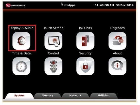
Select Display and audio
Change the volume or brightness as needed.
5. Does UniStream support multiple languages?
Yes, UniStream supports multiple languages. You can add up to 24 languages in your UniStream application.
6. How do I set the RTC in the controller?
There are a few different ways: – via UniLogic: First, establish a PC-PLC connection. Next, select the PLC tab on the UniLogic ribbon, click UniStream Management, and select Set RTC. – via UniApps: Press and hold the top right corner of the HMI screen to enter UniApps, select Time & Date and edit the values. – Via the HMI Time & Date widgets Digital Time and Digital Date.
7. What types of media files are supported?
The following media is supported on UniStream PLCs:
- Images: .bmp, .gif, .jpg,, .png and animated gif. If the dimensions of the picture exceed the resolution of the panel (800×600 for the 10.4” panel, 800×480 for the 7” panel), the image is resized to the panel dimensions
- Audio: The UniStream can play sound files – You can use mp3 and .wav.
- Video: The UniStream can play Video files, .avi and .mp4.
- PDF – The UniStream can display PDF files.
Please note that when a file data size is bigger than 4MB the media file will be downloaded to the external SD card.
8. How do I create trends?
A Trend is the graphical representation of a Data Sample. Therefore, to implement a Trend graph, you must:
- Define a Data Sampler that contains at least one Feed.
Each feed will be represented as a curve on the Trend graph. - Place and configure a Trend widget on a display.
- In your application, use the Data Tags within the Sampler to start, end and pause the data feeds.
In addition to the standard Trend graph widget, where the X axis is time, you can create a graph using the XY Trend widget. This enables you to define units such as millibar or degrees for the X axis.
You can view a video tutorial on this subject on the following link:
http://www.youtube.com/watch?v=pSAm1HVvOO4&list=PLFBq_OH6_be7snAZAycZzQMvAWjHkX9Pz
9. Does UniStream have integrated alarms?
Yes, built-in Alarms are supported by UniLogic 1.14.44 and UniStream OS 1.14.7 and up.
UniStream’ s Alarm system, designed in accordance with ISA ANSI/ISA-18.2-2009 guidelines, provides an efficient method of boosting your application safety level.
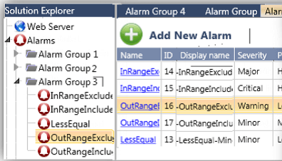
Easily accessible from the Solution Explorer, UniLogic provides a broad range of Alarm features, allowing you to configure Alarms to accommodate different application and alarm types.
The Alarm Banner, displayed on your HMI screens, alerts operators, enabling them to open the Alarm Summary list of events, view status, acknowledge and clear Alarms, and read countermeasure instructions. The Alarm banner may be displayed full-size as shown, with a scrolling window showing active alarms, or may be minimized to a button.
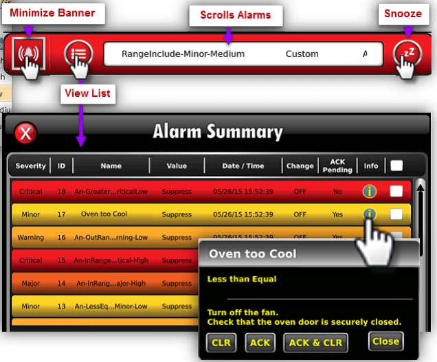
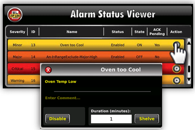
The HMI Toolbox now includes a new widget: the Alarm Status Viewer. This allows convenient Alarms management.
The manager can view Alarm status, enter Comments, Shelve, and Disable Alarms.
Alarm events are logged to the controller’s SD card. You can extract and view these logs via the UniStream Data Converters Suite utility Alarms Log to Excel.
All components of the Alarms system:
Alarm names, alerts, and countermeasure instructions, enjoy multi-language support in all languages including Asian languages.
The components of the Alarm system are a powerful aid to machine builders and automation engineers with applications requiring higher levels of adherence to security standards
Memory allocation (Tags & Structs)
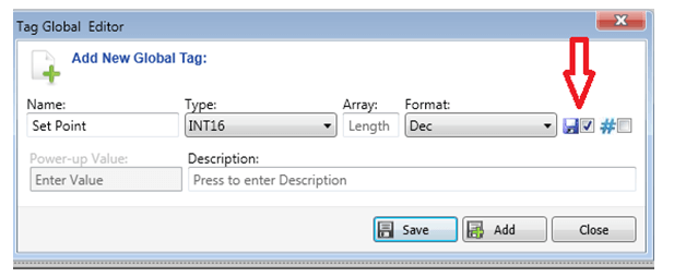
1. What are the differences between retained, power-up value, and initial value?
Retained- By default, UniStream tags are not retained. This means that during power-up, their status will return to zero. Checking “retained” option in the Tag Editor window will change this tag to retain its value at power-up.
Power-Up Values- This option is only available on tags that are not retained. A value is loaded to a tag on power-up of the controller.
Initial Value-This option is only available for retained tags. Option will ONLY be used by the tag upon FIRST DOWNLOAD. After this, the tag retains its last value, even if the same application is re-downloaded or if the unit reboots. The only way to obtain the “initial value” again, another project must be downloaded first, then re-download the intended application.
2. How is the UniStream memory allocated?
UniLogic is based on lexical data tags, not operands. The memory is dynamically allocated depending on the data tags you create, and the data type you link to your tags.
Note, however, that you can create a project containing pre-defined tags, VisiLogic-style. Click the Project tab, and then select New (Pre-defined operands).
The dynamic memory allocation impacts significantly on the performance of the PLC.
Since the precise location of the allocation is not known in advance, the memory is accessed indirectly, usually through a pointer reference.
The memory size is as follows:
- Non Retain memory: 2 MB
- Retained memory: 256K.
Note that Data Tables are made up of STRUCTS, which are tags, and which therefore they share the operand memory.
3. If the UniStream memory is dynamically allocated –lexical tags- how do I assign an address to the tags I wish to read/write using MODBUS communications?
To assign an address to the tags you wish to transmit/receive through MODBUS communication do the following:
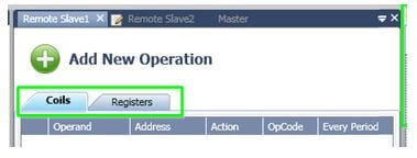
1. Configure the PLC as Master or Slave according to your needs.
2. Add a new operation
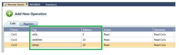
To add an array to be read/write via MODBUS, select a tag within an array.
When you select the tag, you will see a square bracket symbol “ [ “ To send the array, just delete the bracket and press Enter.
3. After linking the tag, add the address in the Address column.
4. When you add the next operand, it will automatically assign the next free address.
4. What is the difference between global and local tags?
Global tags can be created and used throughout the application. You can set them to retain values. Local tags are created within a specific ladder function and are only available in this function, which makes them very handy for use in UDFBs. Local tags are stored in local memory, which increases processing speed. These tags cannot be retained, viewed online, or used in HMI applications.
5. What can cause the loss of TAGS values on power-up?
There are two possible causes:
1. If the tag is not marked as a retained value it will not keep its value after power-up.
2. No battery backup. The reason is typically a weak or missing battery. In UniStream, the indication is when in System Struct General>Battery Low=1.
6. What are Structs?
A struct is a complex data type declaration that defines a physically grouped list of variables (of different data types) to be placed under one name in a block of memory, allowing the different variables to be accessed via a single declared name which returns the same address.
In Unilogic there are four types of Structs:
System Data Tag Structs
System Data Tags service the UniStream system. These tags are organized into Structs.
Automatically-created Structs
These are created by the software when you add elements to your application including:
– Hardware Structs that serve hardware elements such as I/O and COM modules and modems
– Communication structs such as MODBUS and CANopen.
– Function Structs, such as PID.
Timer Structs
These are created when you add a Timer data tag.
User-defined Struct
You define these and reuse them in your program. Each instance may contain different power up values.
UDFB & Library
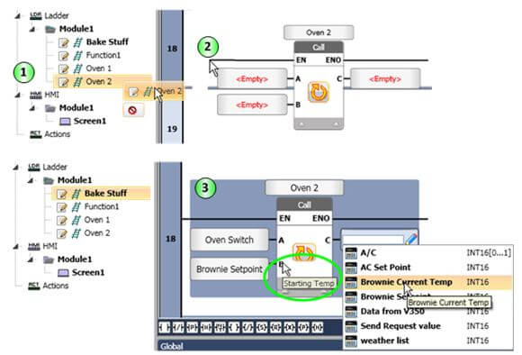
1. What is a User Defined Function Block and what are the advantages of using it?
A User Defined Function Block or UDFB is a function, either written in the Ladder or C Editor, that is designed to perform a specific task, such as control an oven. Any function can be used as a UDFB, with the single exception of the Main function.
In addition to its code, a UDFB may include any of the following:
- Input and output tags to transfer values into and out of the function.
- Local tags, which only exist within that function.
- Global tags, structs, and arrays.
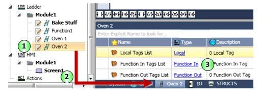
To use a UDFB just Drag & Drop it into the desired function, then link tags to the Function IN and Function Out parameters. Note that you can display the parameter description by mousing over it.
You can access a video tutorial via this link: http://www.youtube.com/watch?v=rb5WyCztLWw&list=PLFBq_OH6_be7snAZAycZzQMvAWjHkX9Pz
2. How do I share my User Defined Function Blocks?
In UniLogic, you can export any Ladder Function or C Function for reuse as a UDFB. In the Solution Explorer, right-click the function name and select Export. UniLogic saves the UDFB as a UniLogic Ladder Export File (*.ulle) which you can import into other programs or share with other programmers. To import a UDFB, right-click on the module you wish to add it to and select Import Function. In addition, you can store all of your UDFBs in the Library, located on the Solution Explorer. The Unitronics forum has a special section for sharing UDFBs: http://forum.unitronics.com/index.php?/forum/70-unilogic-udfbs/
3. What is the Library? How do I use it?
The Library is located on the Solution Explorer. This is where you place all of the Ladder Functions (UDFBs), C Functions, HMI screens, and Web Pages that you want to be available for use throughout all of your UniLogic Projects.
To place UDFBs and HMI screens in the Library, either right-click them in the Solution Explorer and add them to the Library, or place them in the appropriate Library folder, right-click Library, and select Refresh.
Local & Remote IO
1. How do I add and configure I/O modules?
On the Solution Explorer, click Hardware Configuration > Local I/O & COM Modules. The available modules are displayed in the Toolbox.
To add I/O and COM modules to the configuration on the back of the panel, either:
- double-click the desired unit
- highlight it and press Enter
- drag and drop it.
When you add a module, UniLogic creates a struct for that module which contains relevant tags including I/O values and status indications. In addition to the default tag name, you can assign a tag Alias Name; for example, you could assign the Alias Name ‘Light Switch’ to an output tag.
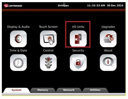
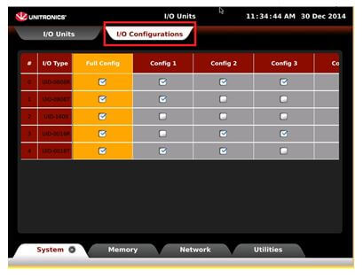
Pre-defined “Configs”
You can create a project with multiple I/O configurations. Then when downloading the application you can select the required configuration by going to UniApp –hold the upper right corner for about 4 seconds- a selecting the I/O Units. Then select the tab I/O configuration and select the desire configuration. The PLC will reset and the selected configuration will be highlighted in yellow.
2. What about I/O Expansion?
The Short and Long Range Local I/O Expansion Kit are also in the Toolbox. You can add one after the final module on the panel. If you don’t want to place any modules on the panel, you can also place it directly next to the CPU.
An Expansion kit enables you to connect up to 85 “Slim” modules to the PLC.
You can add Local Expansion kits according to the following rules:
- After the last module on the panel, you can add up to two short-range kits or one long-range kits.
- You can use the long-range kit after the last module on the panel, or after a short-range kit.
- You can only use one long-range kit per controller.
- After a long-range kit you can add up to two short-range kits.
The use of expansion kits on UniStream is determined by the following table:
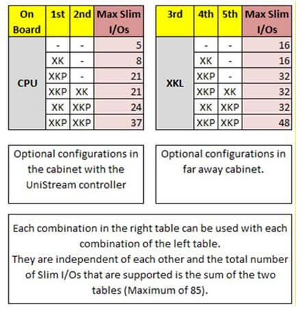
Please note that if you are working with “Wide” I/O modules, consider each one of this modules as 1.5 “Slim” I/O modules.
3. How do I use the Short-Range Local I/O Expansion Kit?
The Expansion Kit allows you to connect a UniStream controller to I/O modules located on a DIN-rail, expanding the number of I/Os connected to a single CPU. The kit comprises a base unit and an end unit. Plug the base unit into the last element on the back of the UniStream HMI panel. The end unit plugs into the first Uni-I/O module in the expansion row. The kit is available either with a power supply, which can support up to16 Uni-I/O modules, or without power, which can support up to 8 Uni-I/O modules.
4. What about Remote I/O Expansion?
You can include Remote I/Os in your application via the EX-RC1 adapter or the EXF-RC15, using files that are ported between VisiLogic and UniLogic.
The EX-RC1 adapter enables you to distribute I/O Expansion Modules throughout your system. The adapter communicates with UniStream devices over CANbus via UniCAN, Unitronics’ proprietary CANbus protocol, and functions as a slave device within that network. Up to 8 EX-RC1 adapters can be included in a project. Each adapter may be connected to up to 8 I/O expansion modules.
The EXF-RC15 is a stand-alone module with high-speed I/Os. It offers 9 digital inputs, 4 digital transistor outputs, and 2 relay outputs. Three inputs can be set via wiring and software to function as high-speed counters/shaft-encoders. The four transistor outputs may function as high-speed PWM/PTO outputs.
You can communicate two kinds of data between UniStream and the EX-RC1 adapter.
I/O Data: to/from the modules that are connected to the adapter.
General Buffer Data: Select this option to send/receive a 16-register long vector of data. These vectors are part of the data struct that UniLogic creates for each adapter that is included in the project.
You can access a video tutorial on this subject on the next link:
http://www.youtube.com/watch?v=APnEBvSqhks&list=PLFBq_OH6_be7snAZAycZzQMvAWjHkX9Pz
Security
1. Can I password protect my application?
Yes, UniStream offers UAC (User Access Control) for HMI elements, and a number of password protection options located under Password Management in the Solution Explorer. They include:
- UniApps Administrator- Password protects UniApps, grants full access, read/write.
- UniApps Guest- Password protects UniApps, grants restricted access, read-only.
- Upload- Prevents unauthorized uploads.
- VNC Full Access- Password protects VNC connection, grants full access, read/write.
- VNC View Only- Password protects VNC connection, grants restricted access, read-only.
- Import/Export App- Password protects Import/Export App from/to USB drive.
2. What password options are available in UniLogic?
The four password options available are the UniApps Administrator password, UniApps Guest password, Upload password, and VNC password. The UniApps Administrator password grants the user full access to UniApps. The UniApps Guest password grants the user restricted read-only access to UniApps. The Upload password will prevent an upload of the UniLogic application without proper verification. The VNC password will prompt the controller to request a password when VNC client requests access.
PID
1. How many PID loops can I have?
You can run up to 64 simultaneous PID loops.
2. When do I need to perform PID Auto-tune?
PID parameters are unique for each specific system. They depend on the hardware of the system. Auto-tune is an independent module. When started, it performs a few On-Off cycles. It then learns the overshoot/undershoot “waves” and, according to their “dimensions”, sets PID parameters. It’s recommended to perform Auto-tune only once – when building and tuning the system. Then it can run for years with these parameters. In some cases, it’s recommended to perform Auto-tune on setpoint, about 10% lower than the real one.
SQL
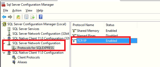
1. I'm not able to establish connection with MS SQL Server – What settings should I check?
- Please make sure that the IP address and Host name of the configured MS SQL server are correct. (In case of using Host name , please make sure to set DNS in UniStream


- Server Name – The server name is the instance name of the SQL.In the example below the name of the SQL instance is SQLEXPRESS


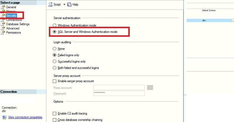
In case there is no SQL instance name (installing the SQL with default instance) the instance name should be MSSQLSERVER. - Please make sure to set the security to “SQL Server and Windows Authentication mode” since UniStream does not support Windows Authentication.


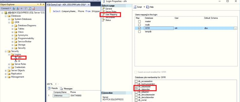
- Please make sure that user and password are correct. Also make sure to give permissions to access the data base such as db_datareader and db_datawriter.


- Please make sure the TCP/IP protocol is enabled in the SQL Server Configuration manager:


- Check Firewall settings that the SQL Server program and the port UDP 1434 are allowed

Installation & Configure and Operate SQL Server
Remote I/Os
1.How do I configure UniStream Remote I/O?
You configure Remote I/Os in UniLogic, using the Hardware Configuration editor.
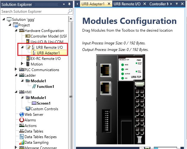
2.How do I connect them to the controller?
- Via Ethernet cable. For exact specifications, refer to the UniStream Remote I/O User Guide in the Technical Library or see UniLogic Help file (F1) unber “URB Remote I/O” .
3.How many Remote I/Os I can connect?
- You can connect up to 8 Remote I/O adapters to a single UniStream, and up to 63 I/O modules to each adapter. However, note that the exact number of I/Os that can be included per adapter is dependent on the specific I/O connected to that specific adapter. For more information, refer to the Remote I/O user manual in the Unitronics Technical Library.
4.New UniStream Remote I/O and existing Uni-I/O – can I use them at the same time?
- You may use both lines in the same application at the same time. Since the two lines communicate via different protocols and physical connections:
They work independently of each other - You can use both lines with the same controller at the same time.
Please note: the adapters and modules of each line are not interchangeable.
You may only use: - Uni-Local Expansion Adapters with Uni-I/O modules
- UniStream Remote I/O Adapters with UniStream Remote I/O modules
5.What standards do they support?
- CE and UL.
6.What is the Operating temperature range?
- The operating temperature range is -40°C to 70°C, where the UL certified temperature range is -20°C to 60°C.
MQTT
1.What is MQTT
- MQTT (Message Queuing Telemetry Transport) is a messaging protocol that runs over TCP/IP, with an publish – subscribe structure.
- A Publisher sends messages according to Topics, to specified Brokers.
- A Broker acts as a switchboard, accepting messages from publishers on specified topics, and sending them to subscribers to those topics.
A Subscriber receives messages from connected Brokers and specified Topics.
2.Does Unitronics support MQTT protocol?
- Yes, Unitronics supports MQTT protocol on the UniStream family.UniStream supports MQTT protocol as a ‘client’ that can both publish, and subscribe to messages.UniStream can:
- Publish data:
- To a defined Broker according to a configured Topic. Periodically, according to a time period set in the configuration
- A periodically, via Ladder Function
- Receive data from a defined Broker on a defined Topic, to which UniStream is subscribed.
- Publish data:
3.Can I connect the UniStream to different Brokers?
- Yes, UniStream can connect to up to of 11 different brokers.
4.Do you support MQTT with Encryption?
- At the moment UniStream support the following encryptions for MQTT:
- MQTT/TCP
- MQTT/SSL – No server authentication
- MQTT/SSL – CA certificate Only
- MQTT/SSL – CA signed server certificate
- MQTT/SSL – self signed server certificates
VFD
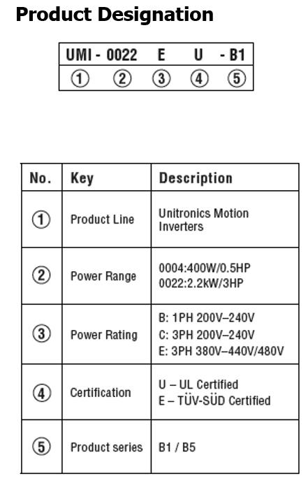
1.What are the article numbers?
Our VFD’s offer 3 variations:
- UMI-B1 Series – with STO – TÜV SÜD certified – 0.4-110 kW
- UMI-B1 Series – UL Certified – 0.4-2.2 kW
- UMI-B5 Series – UL Certified – 0.75-110 kW
Please see the attached excel file for all available article numbers.
2.What are the differences between the models, B1- EU, B1- UL and B5-UL?
There are two main differences:
- Certification
- UMI-B1 EU – TÜV SÜD Safety and CE Certified
- UMI-B1 UL and UMI-B5 UL – UL and CE Certified
- Voltage degree
UMI-B1 EU
230VAC, Single Phase 0.4-2.2 kW
400VAC, Three Phase 0.75-110 kW
UMI-B1 UL
230VAC, Single Phase 0.4-2.2 kW
230VAC, Three Phase 0.4-0.75 kW
460VAC, Three Phase 0.75-2.2 kW
UMI-B5 UL
230VAC, Three Phase 0.75-55 kW
460VAC, Three Phase 1.5-110 kW
For more information, please see excel file with the full differences between the models.
3.Where can I find the user manual?
At Unitronics website, in the Technical Library.
4.Do you have optional parts?
Yes! The optional parts that will be available for our VFDs are:
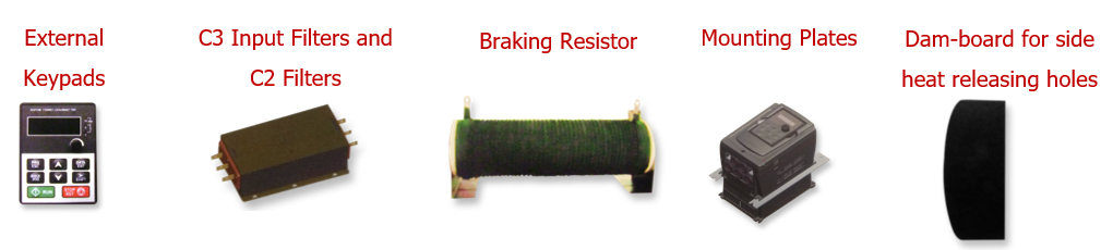
See attached PDF file with articles number. For price look at the excel file attached.
5.When Can I Get One?
Units up to 15kW are in stock.
For additional models, please contact your sales manager for availability.