-
You should tune the Servo under the conditions of the working environment.
-
If there is no need, do not increase gains.
UniLogic enables you to perform single-parameter tuning and run Diagnostics using a motion scope trace that enables you to view the performance of your system.
Once your system hardware is set up and connected, you can import Ready-made Motion code, and use the HMI Tuning screens the code provides to tune your system.
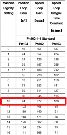
Optimizing servo performance will improve settling time, steady state error, and the overall system responsiveness. In general, proper configuration (system rigidity and inertia ratios) should result in acceptable servo performance that satisfies the application requirements.
|
|
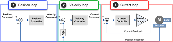
In the closed-loop servo system, every command is based on the previous command's feedback error.
|
3. Position Loop, third loop |
2. Velocity Loop, second loop |
1. Current Loop, internal loop |
|
|
|
|
|
||
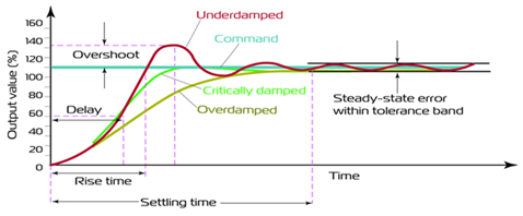
The next graph shows the progression of tuning to minimize Over/undershoot and minimize vibration, to reach a steady state within tolerance limits.
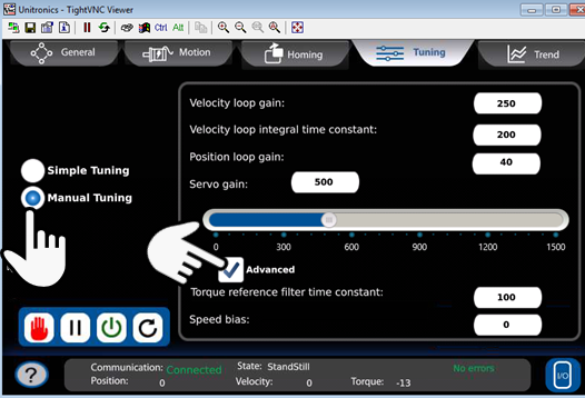
The Ready-made motion code provided by Unitronics includes HMI screens with options for simple and manual tuning.
To access them, select the Tuning tab, and then select Simple or Manual.
Use the Slider to adjust the gain, or enter values in the fields:
Increase “Servo Gain” parameter until it starts fluctuating. (multiply by 2)
Decrease “Servo Gain” (divide the last increased value by 2) until it stops fluctuating

|
|
Select Manual Tuning; note the Advanced checkbox is not checked by default. Touch the Advanced checkbox to reveal additional parameters.
Perform inertia detection (Fn009), note that values are in kg.cm²
Divide that value by motor inertia, as listed in the motor's technical specifications, and enter the resulting value in % into Servo gain (Pn106).
|
|
If you cannot perform the preceding calculation, set the “Servo gain” to 500 |
|
 |
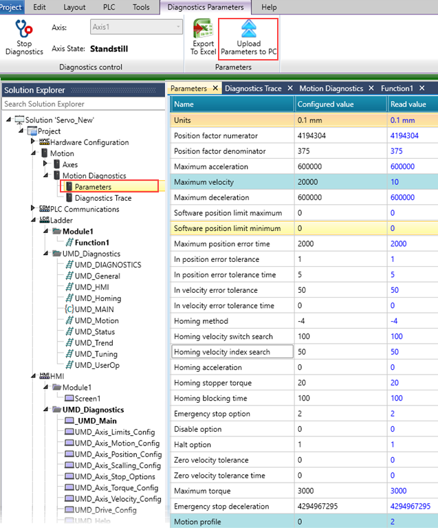
On the Solution Explorer, under Motion Diagnostics, there are the Diagnostic Trace and the Parameters selections.
When you enter online mode, use the Diagnostics trace to see the real-time performance of your system.
Note that you can:
Mouse-over the toolbar on the left of the screen to select View options.
Click on the scope screen and move your cursor back and forth to see different points in the session.
Zoom in and out via your mouse wheel. 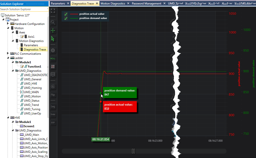
Select Parameters on the Solution Explorer to view actual values.
|
|
Upload Axis Parameters to PC: When you configure an axis, the values you enter in the Axis Struct are written to the axis at power-up. When you enter values from the HMI, the axis functions according to these values, but the values you have entered will be overwritten at power-up.
|
To overwrite the values in the axis struct, use the ribbon option shown below,Upload Axis Parameters to PC.