Multi-Axes MC Functions (EtherCAT)
These functions are compatible with EtherCAT. When you configure the axes Mode to Cyclic a Unitronics EtherCAT master module acts as a motion controller, generating the motion profile and controlling the drives in order to implement Multi-Axes functions such as Camming and Gear.
Multi-Axis Function Blocks enable a synchronized relationship exists between two or more axes. The synchronization can be related to time or position. Often this relationship is between a master axis and one or more slave axes. A master axis can be a virtual axis.
From the state diagram point of view, the multi-axis Function Blocks related to Camming and Gearing can be looked at as a master axis in one state (for instance: MC_MoveContinuous) and the slave axis in a specific synchronized state, called ‘SychronizedMotion’.
Buffer Mode
Buffer Mode is relevant only for Cyclic or Virtual Axis. Relevant diagrams from the PLCopen documention are included at the bottom of this topic.
MC_GearIn
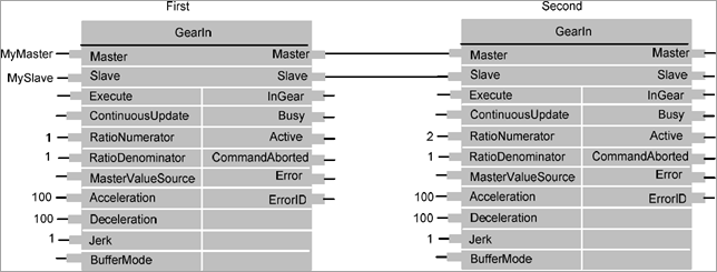
GearIn couples a master axis and a slave axis, with a given gear factor between the velocity of the master axis and of the slave axis.
The slave axis synchronously follows the master axis movement (velocity synchronicity).
The inputs Gear Ratio Numerator and Gear Ratio Denominator enable you to set a specific gear ratio for the movement of the slave axis.
 |
-
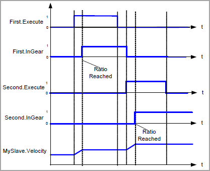
The slave ramps up to the ratio of the master velocity and locks in when this is reached. Any lost distance during synchronization is not caught up.
-
The gearing ratio can be changed while MC_GearIn is running, using a consecutive MC_GearIn command without the necessity to MC_GearOut first
-
After being ‘InGear’, a position locking or just a velocity locking is system specific.
|
The following figures from PLCopen shows the relationship between the axes with Buffer Modes set to 0.
MC_GearOut
GearOut disengages the Slave axis from the Master axis.
|
-
It is assumed that this command is followed by another command, for instance MC_Stop, MC_GearIn, or any other command. If there is no new command, the default condition should be: maintain last velocity.
-
After issuing the FB there is no FB active on the slave axis till the next FB is issued (what can result in problems because no motion command is controlling the axis)
Alternatively one can read the actual velocity via MC_ReadActualVelocity and issue MC_MoveVelocity
on the slave axis with the actual velocity as input.
The FB is here because of compatibility reasons.
|
|
|
|
|
|
A
|
Slave Axis
|
Select the Slave Axis
|
|
B
|
Execute
|
Start disengaging process at the rising edge
|
|
C
|
Done
|
Turns ON when disengaging is completed
|
|
D
|
Busy
|
Bit: when ON, the FB has control over the Axis
|
|
E
|
Error bit
|
Turns ON when an error occurs within the function block
|
|
F
|
Error ID
|
The value indicates the error code.
|
MC_GearInPos
GearInPos commands a gear ratio between the position of the slave and master axes from the synchronization point onwards.
|
-
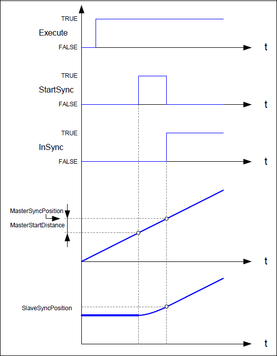
If ‘MasterStartDistance’ is implemented, any previous motion is continued until master crosses ‘Master- SyncPosition’ – ‘MasterStartDistance’ in the correct direction (according to the sign of ‘MasterStartDistance’).
At that point in time the output ‘StartSync’ is set. When a ‘Stop’ command is executed on the
‘Slave’ axis before the synchronization has happened, it inhibits the synchronization and the function block issues ‘CommandAborted’
-
If the ‘MasterStartDistance’ is not specified, the system itself could calculate the set point for ‘StartSync’ based on the other relevant inputs.
-
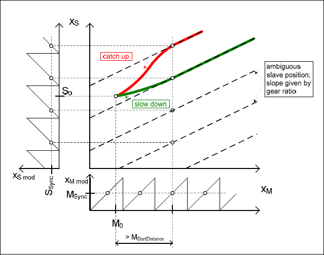
The difference between the ‘SyncModes’ ‘CatchUp’ and ‘SlowDown’ is in the energy needed to synchronize. ‘SlowDown’ costs the lowest energy vs. ‘CatchUp’.
|
|
|
|
|
|
A
|
Master Axis
|
Select the Master Axis
|
|
B
|
Slave Axis
|
Select the Slave Axis
|
|
C
|
Execute
|
Rising Edge starts gearing process
|
|
D
|
Gear Ratio Numerator
|
Gear Ratio Numerator
|
|
E
|
Gear Ratio Denominator
|
Gear Ratio Denominator
|
|
F
|
Master Sync Position
|
The position of the master in the CAM profile where the slave is in-sync with the master. (if the ‘MasterSyncPosition’ does not exist, at the first point of the CAM profile the master and slave are synchronized.)
Note: the inputs acceleration, deceleration and jerk are not added here
|
|
G
|
SlaveSyncPosition
|
Slave Position at which the axes are running in sync
|
|
H
|
SyncMode
|
Defines the way to synchronize mcSIowDown - Synchronize on current slave belt cycle mcCatchUp - Synchronize on next slave belt cycle
|
|
I
|
MasterStartDistance
|
Master Distance for gear in procedure (when the Slave axis is started to get into synchronization)
|
|
J
|
Velocity
|
Maximum Velocity during the time difference ‘StartSync’ and ‘InSync’
|
|
K
|
Acceleration
|
Maximum Acceleration during the time difference ‘Start-Sync’ and ‘InSync’
|
|
L
|
Jerk
|
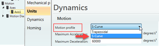
Maximum Jerk during the time difference 'StartSync' and 'InSync' Relevant only if axis motion profile is set as S-Curve
|
|
M
|
Buffer Mode
|
Buffer Mode is relevant only for Cyclic or Virtual Axis.
The default value is 0. This is non-buffered mode, which acts immediately, even if this
interrupts another motion.
Any other value starts buffer mode. This waits till the previous FB completes motion.
Note that all buffered commands will be aborted if the applicable axis moves to the state ‘ErrorStop’. Any subsequent commands will be rejected.
Buffer values
0: Aborting
1: Buffered
2: Blending low
3: Blending previous
4: Blending next
5: Blending high
|
|
N
|
Start Sync
|
Commanded gearing starts
|
|
O
|
InSync
|
Is ON when set value equals commanded value (is calculated set of values derived of master position and gear ratio.)
|
|
P
|
Busy
|
Bit: when ON, the FB has control over the Axis
|
|
Q
|
Active
|
FB is currently controlling the axis
|
|
R
|
Command Aborted
|
Bit: When ON, the FB has been aborted by another command
|
|
S
|
Error bit
|
Turns ON when an error occurs within the function block
|
|
T
|
Error ID
|
The value indicates the error code.
|
The following figure shows the PLCopen Timing Diagram of MC_GearInPos.
The next image shows an example of the difference between ‘SyncModes’ ‘SlowDown’ (green) and ‘CatchUp’ (red) with different initial velocities of the slave.

The next image shows an example of MC_GearInPos where the initial velocity of the slave is in the same direction of the master.
MC_CombineAxes
This Function Block combines the motion of 2 axes into a third axis with selectable combination method. Basically it is a calculation of a new position setpoint based on the 2 position setpoints of the input axes.
This FB is reflected in the state diagram like a synchronized motion type. As application example one can work with a separate profile synchronized to an object on a moving belt, or a rotating knife with flexible covered distance to be cut.
|
To stop the motion, the FB has to be interrupted by another FB issuing a new command
|
|
|
|
|
|
A
|
Master Axis 1
|
Select the first Master Axis
|
|
B
|
Master Axis 2
|
Select the secondMaster Axis
|
|
C
|
Slave Axis
|
Select the Slave Axis
|
|
D
|
Execute
|
Rising Edge Triggers FB
|
|
E
|
Continuous Update
|
If set, input parameters are evaluated at each cycle
|
|
F
|
CombineMode
|
Defines the type of combination applied to AxisOut :
mcAddAxes : Addition of the 2 input axes positions
mcSubAxes : Substraction of the 2 input axes positions
|
|
G
|
Gear Ratio Numerator M1
|
Gear Ratio Numerator Numerator for the gear factor for master axis 1 towards the
slave
|
|
H
|
Gear Ratio Denominator M1
|
Gear Ratio Denominator for the gear factor for master axis 1
|
|
I
|
Gear Ratio Numerator M2
|
Gear Ratio Numerator Numerator for the gear factor for master axis 2 towards the
slave
|
|
J
|
Gear Ratio Denominator M2
|
Gear Ratio Denominator for the gear factor for master axis 2
|
|
K
|
Buffer Mode
|
Buffer Mode is relevant only for Cyclic or Virtual Axis.
The default value is 0. This is non-buffered mode, which acts immediately, even if this
interrupts another motion.
Any other value starts buffer mode. This waits till the previous FB completes motion.
Note that all buffered commands will be aborted if the applicable axis moves to the state ‘ErrorStop’. Any subsequent commands will be rejected.
Buffer values
0: Aborting
1: Buffered
2: Blending low
3: Blending previous
4: Blending next
5: Blending high
|
|
L
|
InSync
|
ON if the set value = the commanded value.
|
|
M
|
Busy
|
Bit: when ON, the FB has control over the Axis
|
|
N
|
Active
|
FB is currently controlling the axis
|
|
O
|
Command Aborted
|
Bit: When ON, the FB has been aborted by another command
|
|
P
|
Error bit
|
Turns ON when an error occurs within the function block
|
|
Q
|
Error ID
|
The value indicates the error code.
|
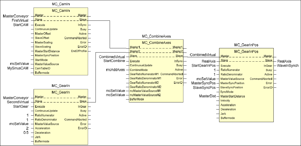
MC_CombineAxes can generate special synchronized movements that are not possible or complex to generate in other ways. In the following example, a CAM FB and the result of a Gear FB are both synchronized to a conveyor master, are added to generate a virtual master for a MC_GearInPos function of the final axis that will execute the movement.
The particular application of this example could be a machine to deposit the icecream waving layers on top of the icecream base travelling through the freezer line in icecream factory. The dosing axis has to synchronize with a waving manner to the conveyor carrying the icecream base block. And it has to do this in a particular starting position and wave phase to achieve the expected result (therefore the GearInPos). With the CAM FB one can define different wave patterns easily (like the one longer in the top of icecream).
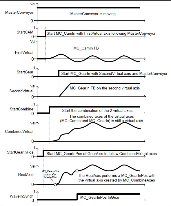
The next image shows the corresponding timing diagram for MC_CombineAxes example.
Camming
This information is an excerpt from PLCopen Safety Part 1 version 2.01, which may be downloaded in its entirety from: https://plcopen.org/downloads
A mechanical cam is a rotating or sliding piece in a mechanical linkage used especially in transforming rotary motion into linear motion or vice versa. It is often a part of a rotating wheel (e.g. an eccentric wheel) or shaft (e.g. a cylinder with an irregular shape) that strikes a lever at one or more points on its circular path. The cam can be a simple tooth, as is used to deliver pulses of power to a steam hammer, for example, or an eccentric disc or other shape that produces a smooth reciprocating (back and forth) motion in the follower, which is a lever making contact with the cam. As such a cam creates a link between a master and one or more slaves in a position / position mode (see figure here under).
With motors and drives one can create the same position / position relationship but in this case via a so-called Cam table listing the positions. So the relationship is converted to software and control.

Basically, one can differentiate between two types of Camming for both modulo and linear (or finite) master axes:
- Periodic mode - repeats the execution of the Cam profile on a continuous basis, even if the CAM profile does not match the modulo. This means that for a modulo axis with modulo is 360 degrees, and the CAM profiles is specifiedfor 90 degrees it will be executed 4 times in a modulo. In reverse mode the profile is executed the inverse way.
- Non-periodic mode – the CAM profile is run only once. If the master position is outside of the Cam profile, the slave axis stays in synchronized motion and keeps the last position. In reverse mode, the CAM profile is not executed after having reached the ‘EndOfProfile’ position. The 90 degrees example above will be run only once.
Camming may be done with several combined cam tables which are executed sequentially, like a ramp-in, a production cycle, and a ramp-out. Between the different cam curves may be a gap (wait for trigger) in the execution. However, one could use the buffered mode or use the output ‘EndOfProfile’ to start the next profile.
CAM table
Camming is done with one table (two dimensional – describing master and slave positions together) or two tables - for master and slave positions separately. The table should be strictly monotonic rising or falling, going both reverse and forward with the master.
It is allowed and possible to change tables while CAM is running and to change elements in the table while the CAM is running.
The generation and filling of the CAM table (master, slave) is performed by an external tool, which is supplier-specific. The coupling of the FB MC_CamIn to the table is also supplier-specific.
Value presentation types
Master and slave axes may have different presentations:
- Absolute values
- Relative to a starting position
- Relative steps (difference to the previous position)
- Equidistant or non-equidistant values.
- Polynomial Format. In this case the cam is described completely in the slave-table. The master-table is zero.
CAM Function Blocks
The advantages of having different Function Blocks for the camming functionality are a more transparent program execution flow and better performance in execution.
Creating a CAM Table
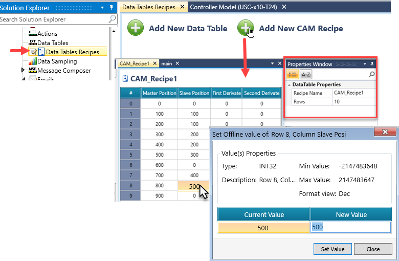
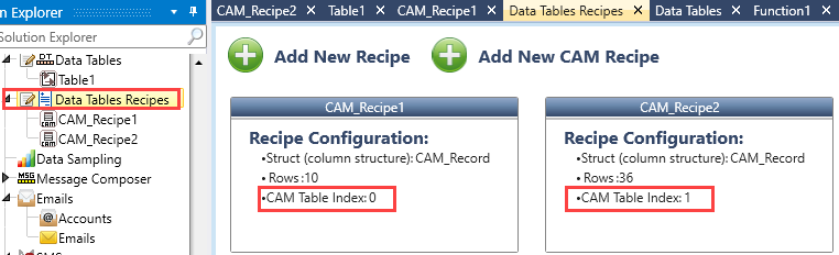
To create CAM tables in UniLogic:
- In the Solution Explorer, click Data Table Recipes.
- Click Add New CAM Recipe; a new CAM table opens.
- Via the Properties window, you can rename the table and set the number of rows.
- Click the CAM table cells to set the values.
UniLogic automatically assigns index numbers to each CAM table. You use these index numbers to identify the table in MC_CamTableSelect.
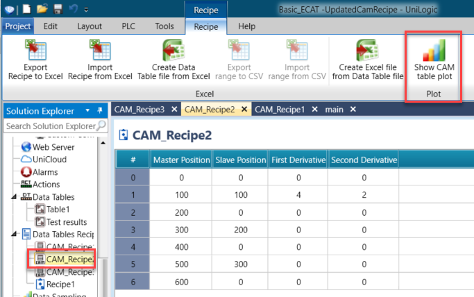
CAM Table Plot
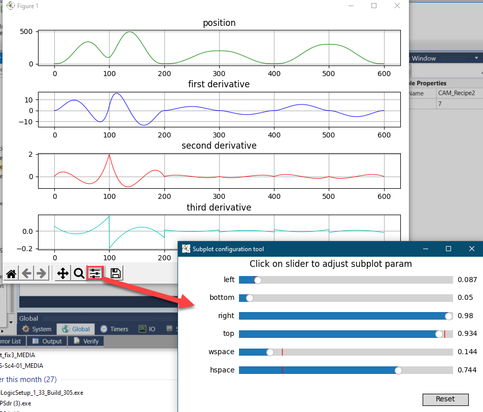
Select a CAM recipe, and from the Recipe tab, select Show CAM Table Plot.
Use the Configuration tool to adjust the view.
|
-
The CAM table must include at least three entries.
-
Each row defines a point in the master/slave position axes and the curve beyond that point. The path between two points is interpolated with a 5th-degree polynomial, which takes two parameters: first and second derivatives (velocity and acceleration).
-
Accelerations and velocities at the start and end points must be zero.
-
The master position of each preceding point should be less than the master position of the following point (this restriction does not apply to slave positions).
|
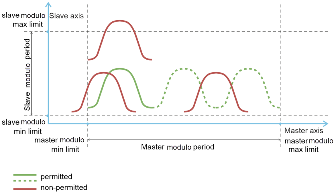
If the master axis operates in modulo mode, the master modulo period must be an integer multiple of the CAM table period.
The minimum modulo limit for the master axis should match the starting point of the CAM table. Additionally, the CAM table range on the slave axis must fall within the slave axis modulo range.
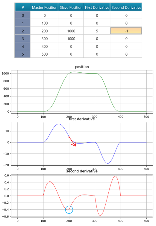
The example below illustrates how the first (velocity) and second (acceleration) derivatives, influence the curve in a CAM table.
The slope angle at Master Position 200 has changed after setting the first derivative parameter value to 5. This adjustment means that the slave axis will reach this point with a nonzero velocity and zero acceleration:

The following image shows a similar effect in the first derivative chart when adjusting the second derivative value.
MC_CamTableSelect
Selects the CAM tables by setting the connections to the relevant tables.
|
A virtual axis can be used as master axis
- MC_CAM_REF is a supplier specific data type
- MC_CAM_ID is a supplier specific data type
- MC_CamTableSelect makes data available. This can include:
-
Starting point of a download of a profile
-
Start to generate a CAM profile
-
When the Done output is SET, the CamTableID is valid and ready for use in a MC_CamIn FB.
-
MasterPositions REAL, List of expressions of the MasterValues for the ‘CamTable’
-
SlavePositions REAL, List of expressions of the SlaveValues for the ‘CamTable’
|
|
|
|
|
|
A
|
Master Axis
|
Select the Master Axis
|
|
B
|
Slave Axis
|
Select the Slave Axis
|
|
C
|
CAM Table Index
|
CAM table index
|
|
D
|
Execute
|
Rising Edge triggers FB
|
|
E
|
Periodic
|
1 = periodic, 0 = non periodic (single-shot)
If set to true, the CAM table will repeat indefinitely
|
|
F
|
Master Absolute
|
1 = absolute; 0 = relative coordinates
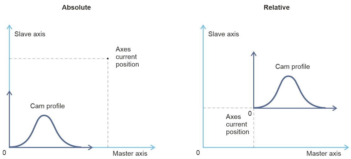
If set to true, the Cam profile origin aligns with the axes origin; otherwise, the Cam profile origin is set to the current axes positions the moment the MC_CamIn execute bit is activated. This can be useful when camming needs to begin from the current position
|
|
G
|
Slave Absolute
|
1 = absolute; 0 = relative coordinates
The Cam table's slave positions are interpreted as relative to the slave's position at the rising edge of CamIn (see image above)
|
|
H
|
Done
|
Pre-selection done
|
|
I
|
Busy
|
Bit: when ON, the FB has control over the Axis
|
|
J
|
Error bit
|
Turns ON when an error occurs within the function block
|
|
K
|
Error ID
|
The value indicates the error code.
|
|
L
|
Cam Table ID
|
Identifier of CAM Table to be used in the MC_CamIn FB
|
MC_CamIn
The Function CamIn engages the Cam.
|
-
It is not required that the master is stationary
-
If the actual master and slave positions do not correspond to the offset values when MC_CamIn is executed, either an error occurs or the system deals with the difference automatically
-
The Cam is placed either absolute or relative to the current master and slave positions.
Absolute: the profile between master and slave is seen as an absolute relationship.
Relative: the relationship between master and slave is in a relative mode.
-
Ramp-in is a supplier specific mode. It can be coupled to additional parameters, such as a master-distance parameter, acceleration parameter, or other supplier specific parameters where the slave to ramp-in into the cam profile (“ flying coupling”)
-
This FB is not merged with the MC_CamTableSelect FB because this separation enables changes on the fly
-
A mechanical analogy to a slave offset is a cam welded with additional constant layer thickness. Because of this the slave positions have a constant offset and the offset could be interpreted as axis offset of the master shaft, if linear guided slave tappets are assumed.
|
|
|
|
|
|
A
|
Master Axis
|
Select the Master Axis
|
|
B
|
Slave Axis
|
Select the Slave Axis
|
|
C
|
Execute
|
Rising Edge triggers FB
|
|
D
|
Master Offset
|
Offset of the master shaft to cam
*see parameter details below
|
|
E
|
Slave Offset
|
Offset of slave table
*see parameter details below
|
|
F
|
Master Scaling
|
Factor for the master profile (default = 1.0).
From the slave point of view, the master overall profile is multiplied by this factor
*see parameter details below
|
|
G
|
Slave Scaling
|
Factor for the slave profile (default = 1.0).
The overall slave profile is multiplied by this factor.
*see parameter details below
|
|
H
|
Master Start Distance
|
The master distance for the slave to start to synchronize to the master.
*see parameter details below
|
|
I
|
Master Sync Position
|
The position of the master in the CAM profile where the slave is in-sync with the master,
(if the 'MasterSyncPosition' does not exist, at the first point of the CAM profile the master and slave are synchronized.)
*see parameter details below
|
|
J
|
CAM table ID
|
Identifier of CAM Table to be used, linked to output of MC_CamTableSelect
|
|
K
|
Buffer Mode
|
Buffer Mode is relevant only for Cyclic or Virtual Axis.
The default value is 0. This is non-buffered mode, which acts immediately, even if this interrupts another motion.
Buffer values
0: Aborting
|
|
L
|
InSync
|
Is ON if the set value = the commanded value.
|
|
M
|
Busy
|
Bit: when ON, the FB has control over the Axis
|
|
N
|
Active
|
FB is currently controlling the axis
|
|
O
|
Command Aborted
|
FB is aborted by another command
|
|
P
|
Error bit
|
Turns ON when an error occurs within the function block
|
|
Q
|
Error ID
|
The value indicates the error code.
|
*Parameter Details:
-
Master Offset: This operates as though the entire master table is shifted by the master offset. For instance, if the original master points are 0, 100, and 200, and a master offset of 50 is applied, the points shift to 50, 150, and 250.
Looking at the slavePos = CAM(masterPos) curve, it will appear identical to the original curve but shifted along the the X-axis by the master offset. If the master axis operates in modulo mode, the maximum point plus the master offset should stay within the modulo range.
-
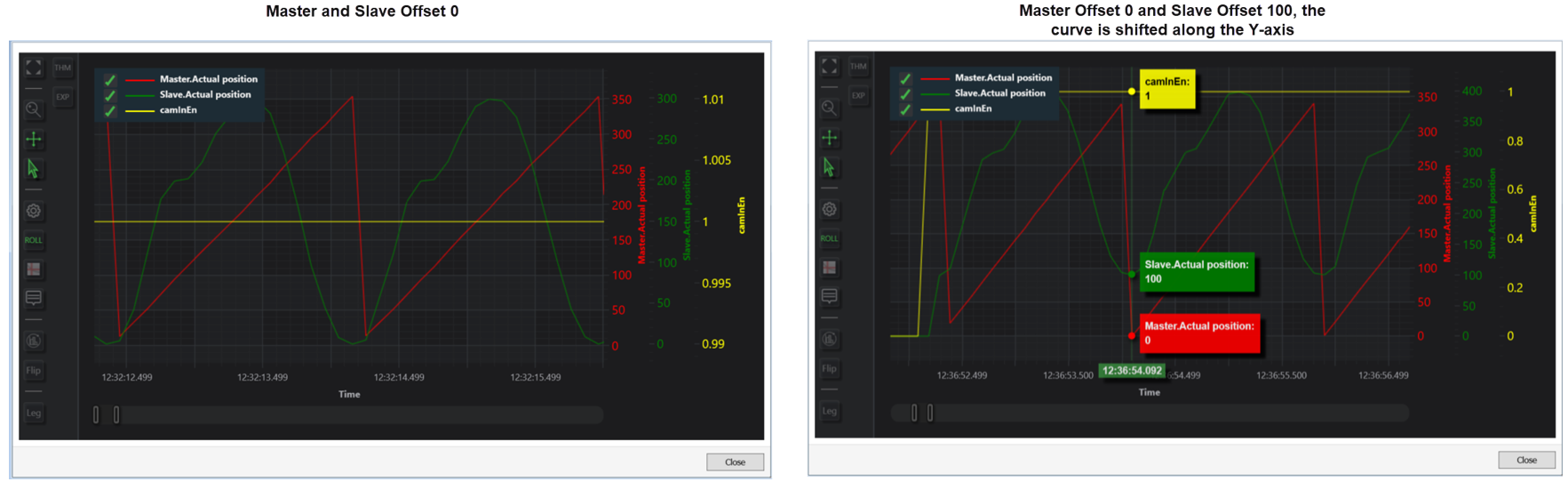
Slave Offset: This operates as if the entire slave table is shifted by the specified slave offset. For instance, if the original slave points are 0, 100, and 0, and a slave offset of 50 is applied, the points shift to 50, 150, and 50.
Looking at the slavePos = CAM(masterPos) curve, it will appear identical to the original curve but shifted along the Y-axis by the slave offset.
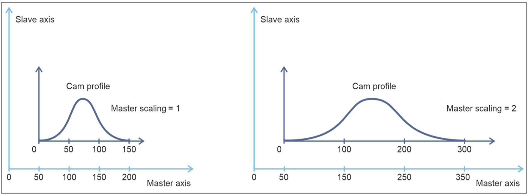
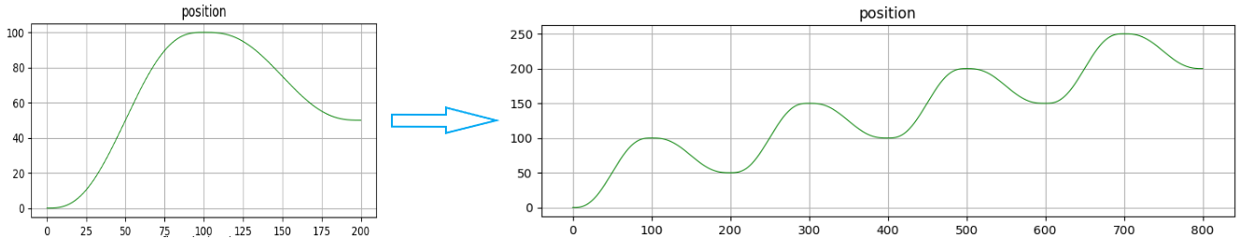
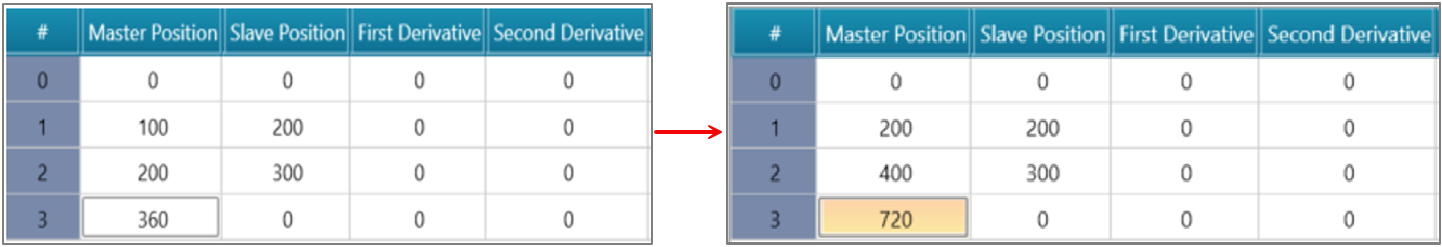
For example, applying a master scaling factor of 2, will make the left CAM table behave identically to the right CAM table.
Note: This calculation is done before the slave offset is added. For instance, if a slave plot is 300, with a slave scaling factor of 2 and a slave offset of 50, the resulting slave plot will be 300x2+50=650.
-
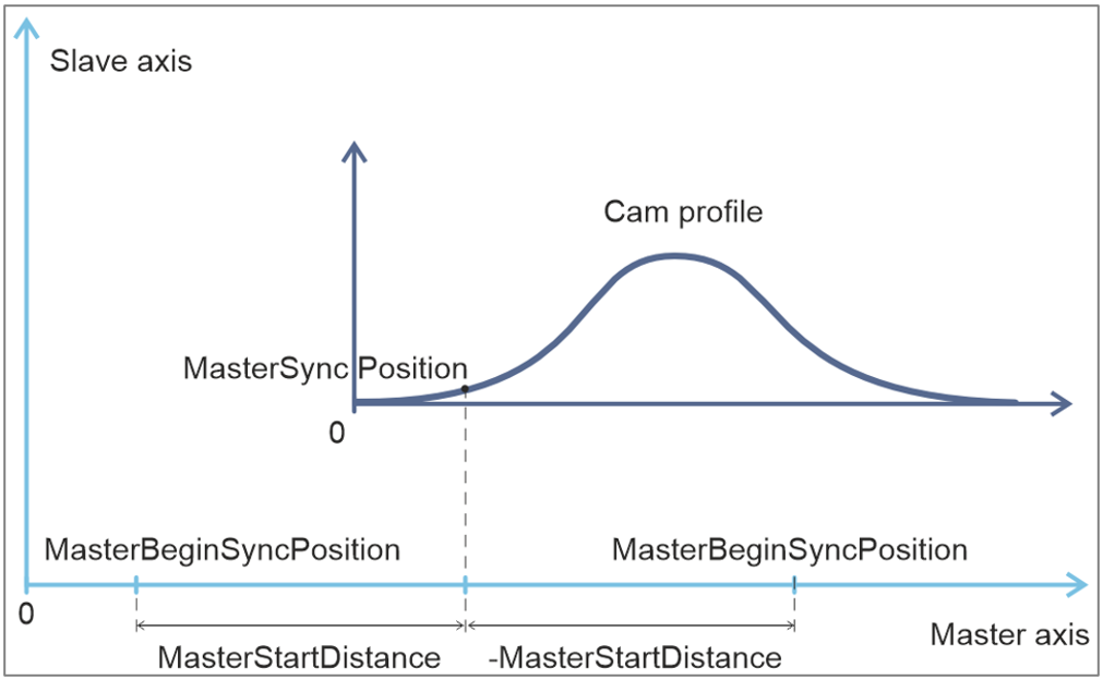
Master Sync Position: Defines the synchronization position on the master axis within the Cam profile's coordinate system. This position must be set within the Cam profile period (see figure here under), and serves as the synchronization point for both master and slave axes, typically corresponding to the first point in the CAM table. There are four possible cases:
-
Master and Slave in sync position: The function block (FB) immediately switches to the InSync state.
-
Master in sync position, Slave not in sync position: The master axis remains at the sync position until the FB moves the slave axis to sync position, then the first case applies.
-
Master not in sync position, Slave in sync position: The slave axis stays at the sync position until the master axis reaches its sync position. The master axis should remain in sync for a few cycles before the FB transitions to InSync.
-
Neither Master nor Slave in sync position:
-
Master Stationary: The FB will wait until the master axis reaches the sync position, after which the second scenario applies.
-
Master moving at constant velocity: The FB moves the slave axis to the sync position to match the master's arrival. The master must maintain constant velocity throughout the process; otherwise, a MASTER_VEL_NOTCONST error will be triggered.
-
Master accelerating: The FB switches to an error state.
- Master Start Distance: Sets the start point for synchronization on the master axis. After crossing this point, the master axis should move at a constant velocity. While the master moves from MasterBeginSyncPosition to MasterSyncPosition, the FB will adjust the slave axis to reach its sync position with corresponding velocity. A negative start distance is also allowed, in which case synchronization will start as the master crosses the start position from right to left. This parameter affects only at the beginning of the camming process. Once the sync position is reached, the curve will remain the same.
MC_CamOut
The CamOut function disengages the Slave axis from the Master axis immediately.
|
-
It is assumed that this command is followed by another command, for instance MC_Stop, MC_GearIn, or any other command. If there is no new command, the default condition should be: maintain last velocity.
-
After issuing the FB there is no FB active on the slave axis till the next FB is issued (what can result in problems because no motion command is controlling the axis). Alternatively one can read the actual velocity via MC_ReadActualVelocity and issue MC_MoveVelocity on the slave axis with the actual velocity as input.
The FB is here because of compatibility reasons
|
|
|
|
|
|
A
|
Slave Axis
|
Select the Slave Axis
|
|
B
|
Execute
|
Rising Edge Triggers FB
|
|
C
|
Done
|
Disengaging complete
|
|
D
|
Busy
|
Bit: when ON, the FB has control over the Axis
|
|
E
|
Error bit
|
Turns ON when an error occurs within the function block
|
|
F
|
Error ID
|
The value indicates the error code.
|
Get Cyclic Mode Error Description (EtherCAT only)
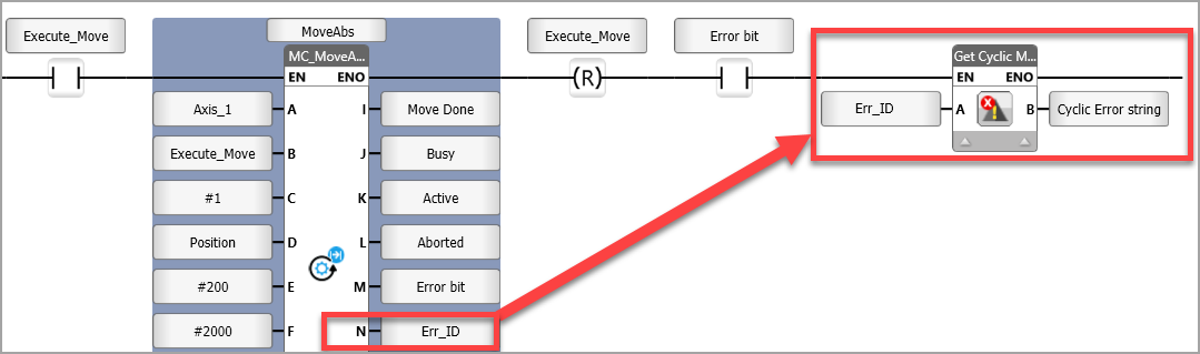
When you configure your application for EtherCAT motion and set an axis to Mode: Cyclic, when the Axis Struct Status parameter indicates Error Stop (bit 7 in the bit array), the Error Stop ID number is written to the Error ID parameter of the MC functions in your program.
You can store the error ID number from an MC function into the Ladder element Get Cyclic Mode Error Description, in order to write the error description into an ASCII tag.
Using the Ladder element Get Cyclic Mode Error Description you can load the ASCII description into the linked ASCII string tag.
Note that all status and error codes are stored into the Error ID parameter of MC functions, not only the cyclic mode errors - however, only the cyclic mode errors will be transferred into the Get Cyclic Mode Error Description function.
Buffer Mode
The following examples and diagrams are examples excerpted from PLCopen documentation.
The Buffer Mode default value is 0. This is non-buffered mode, which acts immediately, even if this interrupts another motion.
Any other value starts buffer mode. This waits till the previous FB completes motion.
Note that all buffered commands will be aborted if the applicable axis moves to the state ‘ErrorStop’. Any subsequent commands will be rejected.
Buffer values
0: Aborting
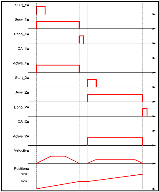
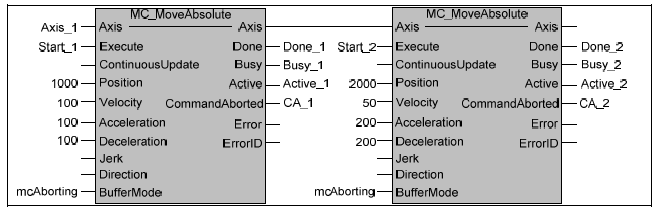
Example 1: Standard behavior of 2 following absolute movements
Basic example with two MC_MoveAbsolute on same axis:

Timing diagram for example above without interference between FB1 and FB2 (‘Aborting’ Mode)
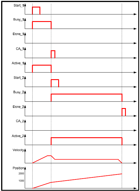
Example 2: ‘Aborting’ motion
Timing diagram for example above with FB2 interrupting FB1 (‘Aborting’ Mode)
Related Topics
EtherCAT Motion
CANopen Motion
Axis Structs
UMD Servo Firmware Update
COM: Servo Functions
COM: Servo Ladder Function Status Codes
MC Function Blocks
MC Function Block Status (Error ID) Codes
Servo: Ready-made Motion Code
Motion: Diagnostics & Tuning
Servo Drive Alarm Codes
Axis Homing Methods