|
|
|
|
|
Enable Communication
|
BIT
|
Turn this ON to allow communications between UniStream and the Servo drive.
This bit is On by default.
This bit must be on in order for the drive to function; when it is OFF the PLC cannot communicate with the drive.
|
|
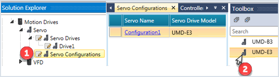
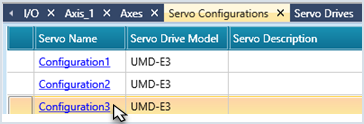
Current Configuration Name
|
STRING-ASCII
|
The name assigned to the Servo drive
|
|
Communication Statistics
|
UINT32
|
[Action successes counter]
|
|
|
UINT32
|
[Action failures counter]
|
|
|
UINT32
|
[Action timeout counter]
|
|
|
UINT32
|
[Message sent]
|
|
|
UINT32
|
[Messages received successfully]
|
|
|
UINT32
|
[Message received erroneously]
|
|
|
UINT32
|
[Failed SDO Index]
|
|
|
UINT32
|
[Failed SDO SubIndex]
|
|
|
UINT32
|
|
|
Function selection switches
|
UINT16
|
[Servo General Parameters1]
|
|
|
UINT16
|
[Servo General Parameters2]
|
|
|
UINT16
|
[Servo General Parameters3]
|
|
|
UINT16
|
[Servo General Parameters4]
|
|
|
UINT16
|
[Servo General Parameters5]
|
|
|
UINT16
|
[Servo General Parameters6]
|
|
|
UINT16
|
[Servo General Parameters7]
|
|
|
UINT16
|
[Servo General Parameters8]
|
|
|
UINT16
|
[Electronic Gear]
|
|
|
UINT16
|
|
|
Parameters of servo gain
|
UINT16
|
[Autotuning Settings]
|
|
|
UINT16
|
[Machine Rigidity Setting]
|
|
|
UINT16
|
[Speed Loop Gain]
|
|
|
UINT16
|
[Speed Loop Integral Time Constant]
|
|
|
UINT16
|
[Position Loop Gain]
|
|
|
UINT16
|
[Torque Reference Filter Time Constant]
|
|
|
UINT16
|
[Servo gain]
|
|
|
UINT16
|
[_2nd Speed Loop Gain]
|
|
|
UINT16
|
[_2nd Speed Loop Integral Time]
|
|
|
UINT16
|
[_2nd Position Loop Gain]
|
|
|
UINT16
|
[_2nd Torque Reference Filter Time Constant]
|
|
|
UINT16
|
[Speed Bias]
|
|
|
UINT16
|
[Speed Feedforward]
|
|
|
UINT16
|
[Speed Feedforward Filter Time Constant]
|
|
|
UINT16
|
[Torque Feedforward]
|
|
|
UINT16
|
[Torque Feedforward Filter Time Constant]
|
|
|
UINT16
|
[P/PI Switching Condition]
|
|
|
UINT16
|
[Torque Switching Threshold]
|
|
|
UINT16
|
[Offset Counter Switching Threshold]
|
|
|
UINT16
|
[Setting Acceleration Speed Switching Threshold]
|
|
|
UINT16
|
[Setting Speed Switching Threshold]
|
|
|
UINT16
|
[Gain Switching Condition]
|
|
|
UINT16
|
[Gain Switching Waiting Time]
|
|
|
UINT16
|
[Switch Threshold Level]
|
|
|
UINT16
|
[Actual Speed Threshold]
|
|
|
UINT16
|
[Position Loop Gain Switching Time]
|
|
|
UINT16
|
[Hysteresis Switching]
|
|
|
UINT16
|
[Low Speed Detection Filter]
|
|
|
UINT16
|
[Speed Gain Acceleration Relationship During Online Autotuning]
|
|
|
UINT16
|
[Low Speed Correction Coefficient]
|
|
|
UINT16
|
[Friction Load]
|
|
|
UINT16
|
[Speed Lag Ring of Friction Compensation]
|
|
|
UINT16
|
[Viscous Friction Load]
|
|
|
UINT16
|
[Notch Filters 1 Trap Width]
|
|
|
UINT16
|
[Notch Filters 2 Trap Width]
|
|
|
UINT16
|
|
|
Position control related parameters
|
UINT16
|
[PG Divider]
|
|
|
UINT16
|
[_16 Bit 1st Electronic Gear Numerator]
|
|
|
UINT16
|
[_16 Bit Electronic Gear Denominator]
|
|
|
UINT16
|
[_16 Bit 2nd Electronic Gear Numerator]
|
|
|
UINT16
|
[Position Reference Filter Time Constant]
|
|
|
UINT16
|
[Position Reference Filter Mode Selection]
|
|
|
UINT16
|
|
|
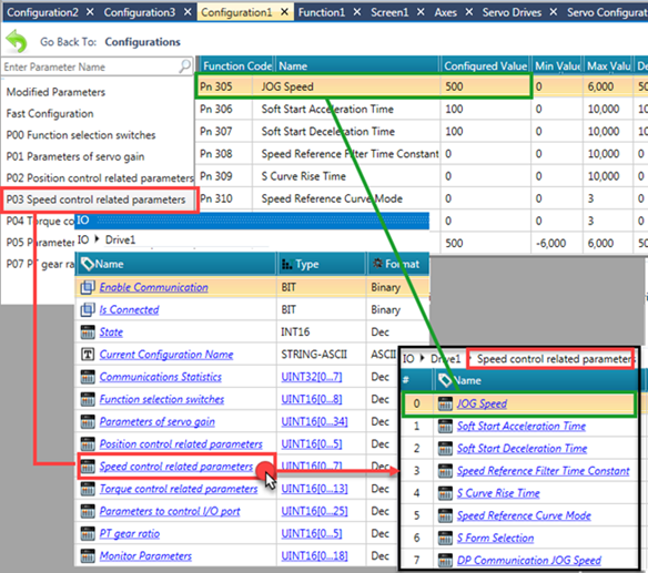
Speed control related parameters
|
UINT16
|
[JOG Speed]
|
|
|
UINT16
|
[Soft Start Acceleration Time]
|
|
|
UINT16
|
[Soft Start Deceleration Time]
|
|
|
UINT16
|
[Speed Reference Filter Time Constant]
|
|
|
UINT16
|
[S Curve Rise Time]
|
|
|
UINT16
|
[Speed Reference Curve Mode]
|
|
|
UINT16
|
[S Form Selection]
|
|
|
UINT16
|
[DP Communication JOG Speed]
|
|
|
UINT16
|
|
|
Torque control related parameters
|
UINT16
|
[Forward Internal Torque Limit]
|
|
|
UINT16
|
[Reverse Internal Torque Limit]
|
|
|
UINT16
|
[Forward External Torque Limit]
|
|
|
UINT16
|
[Reverse External Torque Limit]
|
|
|
UINT16
|
[Reversal Connections Braking Torque Limit]
|
|
|
UINT16
|
[Speed Limit During Torque Control]
|
|
|
UINT16
|
[_1st Notch Filter Frequency]
|
|
|
UINT16
|
[_1st Notch Filter Depth]
|
|
|
UINT16
|
[_2nd Notch Filter Frequency]
|
|
|
UINT16
|
[_2nd Notch Filter Depth]
|
|
|
UINT16
|
[Frequency of Low Frequency Jitter]
|
|
|
UINT16
|
[Damp of Low Frequency Jitter]
|
|
|
UINT16
|
[Torque Control Delay Time]
|
|
|
UINT16
|
[Torque Control Speed Lag]
|
|
|
UINT16
|
|
|
Parameters to control I/O port
|
UINT16
|
[Positioning Error]
|
|
|
UINT16
|
[Coincidence Difference]
|
|
|
UINT16
|
[Zero Clamp Speed]
|
|
|
UINT16
|
[Rotation Detection Speed]
|
|
|
UINT16
|
[Position Error Pulse Counter Overflow Alarm Selection]
|
|
|
UINT16
|
[Servo On Waiting Time]
|
|
|
UINT16
|
[Basic Waiting Flow]
|
|
|
UINT16
|
[Brake Waiting Speed]
|
|
|
UINT16
|
[Brake Waiting Time]
|
|
|
UINT16
|
[Inputs Selection Group1]
|
|
|
UINT16
|
[Inputs Selection Group2]
|
|
|
UINT16
|
[Outputs Selection]
|
|
|
UINT16
|
[Inputs Enable Group1]
|
|
|
UINT16
|
[Inputs Enable Group2]
|
|
|
UINT16
|
[Input Port Filter]
|
|
|
UINT16
|
[Alarm Port Filter]
|
|
|
UINT16
|
[Inputs Inverse Group1]
|
|
|
UINT16
|
[Inputs Inverse Group2]
|
|
|
UINT16
|
[Dynamic Brake Time]
|
|
|
UINT16
|
[Serial Encoder Error Time]
|
|
|
UINT16
|
[Position Complete Time]
|
|
|
UINT16
|
[Regenerative Resistor]
|
|
|
UINT16
|
[Overload Alarm Threshold]
|
|
|
UINT16
|
[Outputs Inverse]
|
|
|
UINT16
|
[Torque Detection Signal Output Threshold Value]
|
|
|
UINT16
|
[Torque Detection Output Signal Time]
|
|
|
UINT16
|
|
|
PT gear ratio
|
UINT16
|
[_32 Bit 1st Electronic Gear Numerator (H)]
|
|
|
UINT16
|
[_32 Bit 1st Electronic Gear Numerator (L)]
|
|
|
UINT16
|
[_32 Bit Electronic Gear Denominator (H)]
|
|
|
UINT16
|
[_32 Bit Electronic Gear Denominator (L)]
|
|
|
UINT16
|
[_32 Bit 2nd Electronic Gear Numerator (H)]
|
|
|
UINT16
|
[_32 Bit 2nd Electronic Gear Numerator (L)]
|
|
|
UINT16
|
|
|
Monitor Parameters
|
UINT16
|
[Actual servomotor speed]
|
|
|
UINT16
|
[Input speed reference]
|
|
|
UINT16
|
[Input torque reference (with respect to rated torque)]
|
|
|
UINT16
|
[Internal torque reference (with respect to rated torque)]
|
|
|
UINT16
|
[Number of encoder rotation angle pulses]
|
|
|
UINT16
|
[Input signal monitor]
|
|
|
UINT16
|
[Encoder signal monitor]
|
|
|
UINT16
|
[Output signal monitor]
|
|
|
UINT16
|
[Frequency given by pulse]
|
|
|
UINT16
|
[Number of servomotor rotation pulses]
|
|
|
UINT16
|
[Pulse rate of servomotor rotated]
|
|
|
UINT16
|
[Error pulse counter lower 16 digit]
|
|
|
UINT16
|
[Error pulse counter higher 16 digit]
|
|
|
UINT16
|
[Number of pulses given]
|
|
|
UINT16
|
[Number of pulses given (x10000)]
|
|
|
UINT16
|
[Load inertia percentage]
|
|
|
UINT16
|
[Servomotor overload ratio]
|
|
|
UINT16
|
[Encoder EEPROM saves motor and encoder types and correlation information]
|
|
|
UINT16
|
[Nikon Encode internal Temperature]
|