These MC functions are compatible with both CANopen and EtherCAT. Multi-Axes MC Functions are compatible with EtherCAT.
The MC function blocks are listed under Motion Control in the Ladder Toolbox.
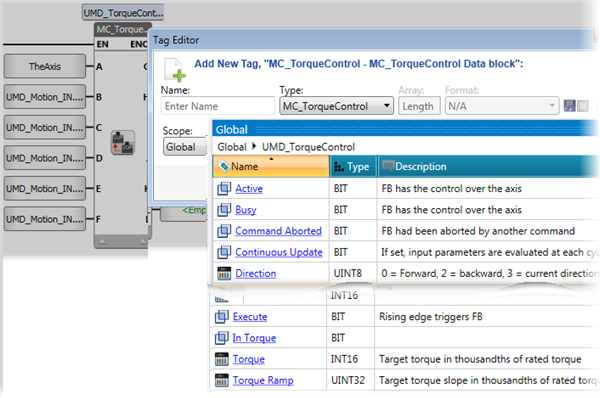
Note that each MC FB is automatically allocated a data block - a specific, reserved memory section - when you include it in your program. A data block is linked to a struct; you assign a tag for the struct name when you include the FB in your project. The parameters in these structs are read-only.
![]() Note that the parameters of the data block will vary according to the UMD drive model. For example, UMD drives that support TouchProbe will display parameters for probe number and latch window.
Note that the parameters of the data block will vary according to the UMD drive model. For example, UMD drives that support TouchProbe will display parameters for probe number and latch window.
|
In accordance with PLCopen standards, MC FBs have outputs that are visible in the Ladder. You do not have to link operands to these outputs. |
 |
 |
These are general notes regarding MC function blocks:
|
This FB controls the power flow to the Axis (On or Off).
It activates at the rising edge of the Enable bit.
|
|
|
|
Parameter Name |
Purpose |
|
A |
Axis |
Select the Axis you want to power |
|
B |
Enable |
When ON, power is being supplied to the drive that the Axis is linked to |
|
C |
Status |
Effective State of the Power phase |
|
D |
A Valid set of outputs is available |
If true, a valid set of outputs is available for the FB |
|
E |
Error bit |
Turns ON when an error occurs within the function block |
|
F |
Error ID |
The value indicates the error code. |
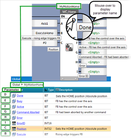
This Function Block commands the axis to perform the «search home» sequence. This is set in Axis> Homing.
The ‘Position’ input is MC Powered to set the absolute position when reference signal is detected. This Function Block completes at ‘Standstill’ if it was started in ‘Standstill’
|
|
Parameter Name |
Purpose |
|
A |
Axis |
Select the Axis you want to power |
|
B |
Execute |
Rising Edge Triggers FB |
|
C |
Position |
Sets the HOME position (Absolute position when the reference signal is detected) |
|
D |
Done |
Bit: when ON: axis is in the Home position |
|
E |
Busy |
FB is currently controlling the axis |
|
F |
Active |
FB is currently controlling the axis |
|
G |
Command Aborted |
Bit: when ON, the FB has been aborted by another command |
|
H |
Error bit |
Turns ON when an error occurs within the function block |
|
I |
Error ID |
The value indicates the error code. |
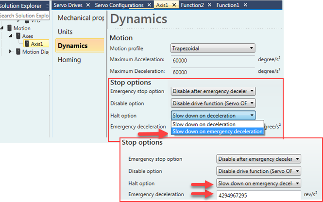
This Function Block decelerates the axis according to the emergency deceleration defined in the axis configuration, commanding a controlled motion stop and transferring the axis to the state ‘Stopping’. It aborts any ongoing Function Block execution. While the axis is in state ‘Stopping’, no other FB can perform any motion on the same axis.
After the axis has reached ‘Velocity’ zero, the ‘Done’ output immediately turns ON.
The axis remains in the state ‘Stopping’ as long as ‘Execute’ is still TRUE or ‘Velocity’ zero is not yet reached. As soon as ‘Done’ turns ON and ‘Execute’ is OFF, the axis goes to state ‘Standstill’.
|
|
Parameter Name |
Purpose |
|
A |
Axis |
Select the Axis you want to control |
|
B |
Execute |
Rising Edge Triggers FB |
|
C |
Jerk |
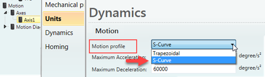
Value for Jerk. Relevant only if S-curve profile has been selected |
|
D |
Done |
Bit: when ON, Zero Velocity Reached |
|
E |
Busy |
Bit: when ON, the FB has control over the Axis |
|
F |
Command Aborted |
Bit: When ON, the FB has been aborted by power being switched off, there is no other way to abort a Stop command |
|
G |
Error bit |
Turns ON when an error occurs within the function block |
|
H |
Error ID |
The value indicates the error code. |
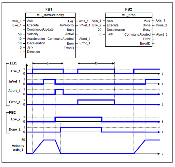
The image below shows the behavior of MC Stop in combination with a MC MoveVelocity.
A rotating axis is ramped down with FB MC Stop.
The axis rejects motion commands as long as MC Stop parameter ‘Execute’ = ON.
FB MC MoveVelocity reports an error indicating the busy MC Stop command
This Function Block decelerates the axis according to the rate of deceleration you define in parameter C, commanding a controlled motion stop and transferring the axis to the state 'Standstill'.
The axis is moved to the state ‘DiscreteMotion’, until the velocity is zero. With the ‘Done’ output set, the state is transferred to ‘Standstill’.
|
|
|
|
Parameter Name |
Purpose |
|
A |
Axis |
Select the Axis you want to control |
|
B |
Execute |
Rising Edge Triggers FB |
|
C |
Deceleration |
Value for deceleration |
|
D |
Jerk |
Value of the ‘Jerk’ [u/s3]. (always positive). Relevant only if S-curve profile has been selected in the Axis parameters Axis> Dynamics>Motion>Motion Profile; if S-curve has not been selected, this is ignored.Relevant only if S-curve profile has been selected in the Axis parameters Axis> Dynamics>Motion>Motion Profile; if S-curve has not been selected, this is ignored.
|
|
E |
Buffer Mode |
Buffer Mode is relevant only for Cyclic or Virtual Axis. Note that all buffered commands will be aborted if the applicable axis moves to the state ‘ErrorStop’. Any subsequent commands will be rejected. Buffer values |
|
F |
Done |
Bit: when ON, Axis has halted successfully |
|
G |
Busy |
Bit: when ON, the FB has control over the Axis |
|
H |
Active |
FB is currently controlling the axis |
|
I |
Command Aborted |
Bit: When ON, the FB has been aborted by another command |
|
J |
Error bit |
Turns ON when an error occurs within the function block |
|
K |
Error ID |
The value indicates the error code. |
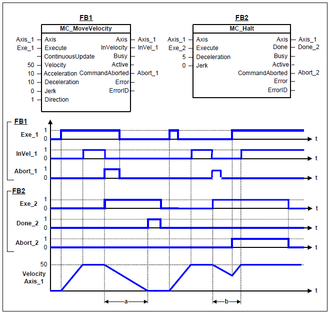
The example below shows the behavior in combination with a MC_MoveVelocity.
A rotating axis is ramped down with Function Block MC_Halt
Another motion command overrides the MC_Halt command. MC_Halt allows this, in contrast to MC_Stop.
The axis can accelerate again without reaching ‘Standstill’.
This Function Block commands a controlled motion to a specified absolute position.
This action completes with velocity zero if no further actions are pending.
|
|
Parameter Name |
Purpose |
|
A |
Axis |
Select the Axis you want to control |
|
B |
Execute |
Rising Edge Triggers FB |
|
C |
Continuous Update |
If Set, Input parameters are evaluated at each cycle |
|
D |
Position |
Commanded ‘Position’ for the motion (in technical unit [u]) (negative or positive) |
|
E |
Velocity |
Value of the maximum ‘Velocity’ (not necessarily reached) [u/s]. |
|
F |
Acceleration |
Value of the ‘Acceleration’ (always positive) (increasing energy of the motor) [u/s2] |
|
G |
Deceleration |
Value of the ‘Deceleration’ (always positive) (decreasing energy of the motor) [u/s2]. If ‘Deceleration’ = 0, acceleration value will be used.
|
|
H |
Jerk |
Value of the ‘Jerk’ [u/s3]. (always positive). Relevant only if S-curve profile has been selected in the Axis parameters Axis> Dynamics>Motion>Motion Profile; if S-curve has not been selected, this is ignored.Relevant only if S-curve profile has been selected in the Axis parameters Axis> Dynamics>Motion>Motion Profile; if S-curve has not been selected, this is ignored.
|
|
I |
Direction |
Direction - Relevant for rotary axis only, ignored for linear axis 0 = Forward |
|
J |
Buffer Mode |
Buffer Mode is relevant only for Cyclic or Virtual Axis. Note that all buffered commands will be aborted if the applicable axis moves to the state ‘ErrorStop’. Any subsequent commands will be rejected. Buffer values |
|
K |
Done |
Bit: turns ON when Axis has reached position |
|
L |
Busy |
Bit: when ON, the FB has control over the Axis |
|
M |
Active |
FB is currently controlling the axis |
|
N |
Command Aborted |
Bit: When ON, the FB has been aborted by another command |
|
O |
Error bit |
Turns ON when an error occurs within the function block |
|
P |
Error ID |
The value indicates the error code. |
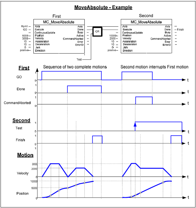
The following figure shows two examples of the combination of two Move Absolute FBs:
The left part of the timing diagram illustrates the case if the Second FB is called after the First one.
If First reaches the commanded position of 6000 (and the velocity is 0) then the output ‘Done’ causes the Second FB
to move to the ‘Position’ 10000.
The right part of the timing diagram illustrates the case if the Second FB starts the execution while the First FB is still executing.
In this case the First motion is interrupted and aborted by the Test signal during the constant velocity of the First FB.
The Second FB moves directly to the position 10000 although the position of 6000 is not yet reached.
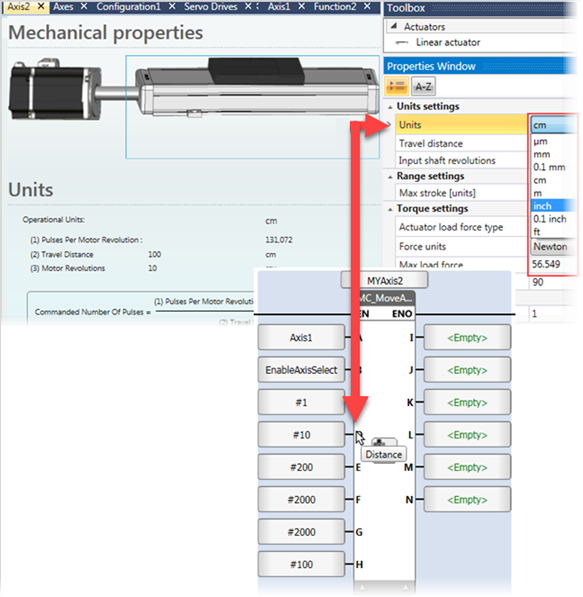
This Function Block commands a controlled motion of a specified distance relative to the set position at the time of the execution.
This action completes with velocity zero.
|
|
Parameter Name |
Purpose |
|
A |
Axis |
Select the Axis you want to control |
|
B |
Execute |
Rising Edge Triggers FB |
|
C |
Continuous Update |
If Set, Input parameters are evaluated at each cycle |
|
D |
Distance |
Commanded ‘Position’ for the motion (in technical unit [u]) (negative or positive) |
|
E |
Velocity |
Value of the maximum ‘Velocity’ (not necessarily reached) [u/s]. |
|
F |
Acceleration |
Value of the ‘Acceleration’ (always positive) (increasing energy of the motor) [u/s2] |
|
G |
Deceleration |
Value of the ‘Deceleration’ (always positive) (decreasing energy of the motor) [u/s2].
|
|
H |
Jerk |
Value of the ‘Jerk’ [u/s3]. (always positive). Relevant only if S-curve profile has been selected in the Axis parameters Axis> Dynamics>Motion>Motion Profile; if S-curve has not been selected, this is ignored.Relevant only if S-curve profile has been selected in the Axis parameters Axis> Dynamics>Motion>Motion Profile; if S-curve has not been selected, this is ignored.
|
|
I |
Buffer Mode |
Buffer Mode is relevant only for Cyclic or Virtual Axis. Note that all buffered commands will be aborted if the applicable axis moves to the state ‘ErrorStop’. Any subsequent commands will be rejected. Buffer values |
|
KJ |
Done |
Bit: turns ON when Axis has reached the commanded distance |
|
L |
Busy |
Bit: when ON, the FB has control over the Axis |
|
M |
Active |
FB is currently controlling the axis |
|
N |
Command Aborted |
Bit: When ON, the FB has been aborted by another command |
|
O |
Error bit |
Turns ON when an error occurs within the function block |
|
P |
Error ID |
The value indicates the error code. |
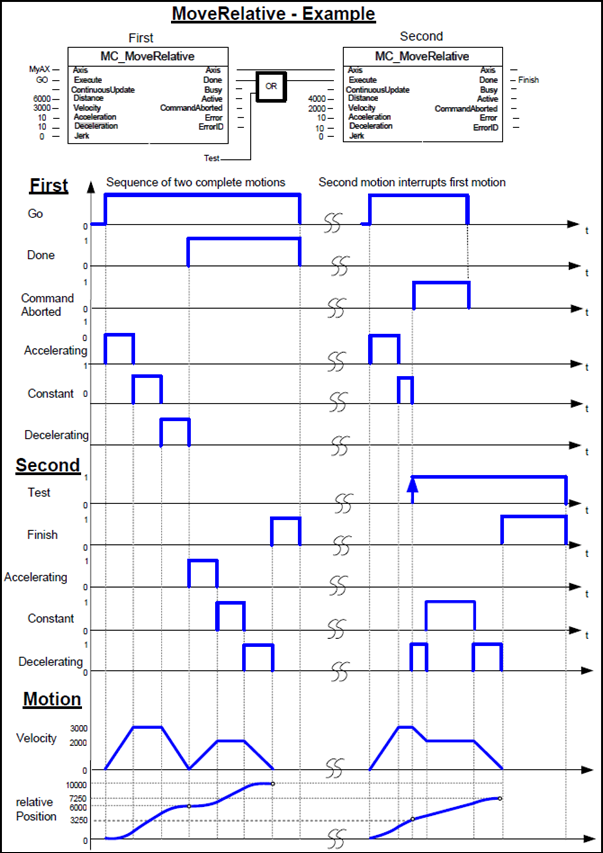
The following figure shows the example of the combination of two relative move Function Blocks
The left part of the timing diagram illustrates the case if the Second FB is called after the First one. If First reaches the commanded distance 6000 (and the velocity is 0) then the output ‘Done’ causes the Second FB to move the commanded distance 4000 and moves the axis to the resulting position of 10000.
The right part of the timing diagram illustrates the case if the Second move Function Blocks starts the execution while the First FB is still executing. In this case the First motion is interrupted and aborted by the Test signal during the constant velocity of the First FB. The Second FB adds on the actual position of 3250 the distance 4000 and moves the axis to the resulting position of 7250.
This Function Block commands a controlled motion of a specified relative distance additional to the most recent commanded position in the axis state ‘DiscreteMotion’. The most recent commanded position may be the result of a previous MC_MoveAdditive motion which was aborted.
If the FB is activated in the axis state ‘ContinuousMotion’, the specified relative distance is added to the set position at the time of the execution.
|
|
|
|
Parameter Name |
Purpose |
|
A |
Axis |
Select the Axis you want to control |
|
B |
Execute |
Rising Edge Triggers FB |
|
C |
Continuous Update |
If Set, Input parameters are evaluated at each cycle |
|
D |
Distance |
Commanded ‘Position’ for the motion (in technical unit [u]) (negative or positive) |
|
E |
Velocity |
Value of the maximum ‘Velocity’ (not necessarily reached) [u/s]. |
|
F |
Acceleration |
Value of the ‘Acceleration’ (always positive) (increasing energy of the motor) [u/s2] |
|
G |
Deceleration |
Value of the ‘Deceleration’ (always positive) (decreasing energy of the motor) [u/s2]. |
|
H |
Jerk |
Value of the ‘Jerk’ [u/s3]. (always positive). Relevant only if S-curve profile has been selected in the Axis parameters Axis> Dynamics>Motion>Motion Profile; if S-curve has not been selected, this is ignored.Relevant only if S-curve profile has been selected in the Axis parameters Axis> Dynamics>Motion>Motion Profile; if S-curve has not been selected, this is ignored.
|
|
I |
Done |
Bit: turns ON when Axis has reached the commanded distance |
|
J |
Busy |
Bit: when ON, the FB has control over the Axis |
|
K |
Active |
FB is currently controlling the axis |
|
L |
Command Aborted |
Bit: When ON, the FB has been aborted by another command |
|
M |
Error bit |
Turns ON when an error occurs within the function block |
|
N |
Error ID |
The value indicates the error code. |
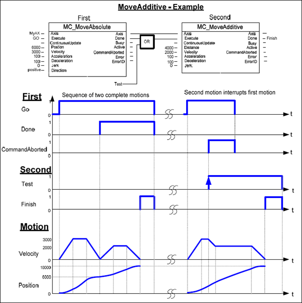
The following figure shows two examples of the combination of two Function Blocks while the axis is in ‘Discrete Motion’ state:
The left part of the timing diagram illustrates the case if the Second FB is called after the First one.
If First reaches the commanded distance 6000 (and the velocity is 0) then the output ‘Done’ causes the Second FB to move the commanded distance 4000 and moves the axis to the resulting position of 10000.
The right part of the timing diagram illustrates the case if the Second move Function Blocks starts the execution while the First FB is still executing. In this case the First motion is interrupted and aborted by the Test signal during the constant velocity of the First FB. The Second FB adds on the previous commanded position of 6000 the distance 4000 and moves the axis to the resulting position of 10000.
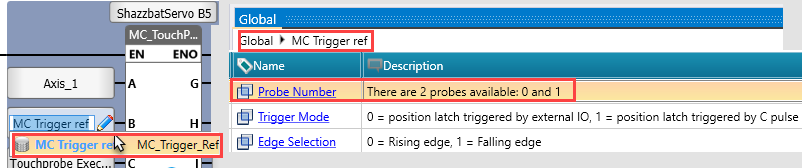
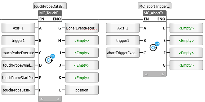
Certain Unitronics Servo drives support Touchprobe. Their function is supported by MC_TouchProbe, and MC_AbortTriggerMC_TouchProbe, and MC_AbortTrigger.
Refer to the drive manual for probe wiring instructions.
|
|
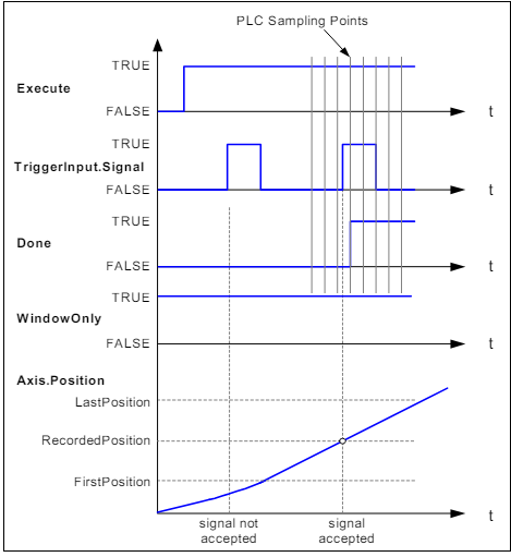
This Function Block is used to record an axis position at a trigger event. It records an axis position at the point in time of a digital signal (measuring probe function).
|
|
|
|
Parameter Name |
Purpose |
|
A |
Axis |
Select the Axis you want to control. |
|
B |
Trigger Input |
Click to select the MC Trigger_Ref block. This contains the Probe number; in your application, store 0 to select the first probe and 1 to select the second. Refer to the drive manual for probe wiring instructions. You can also use MC Trigger_Ref to switch the trigger mode to C pulse, and to change the Edge Selection on the fly in your application. |
|
C |
Execute |
Rising Edge triggers the FB. Note that Execute bit cannot be used to abort the trigger event. Use the MC_AbortTrigger function. |
|
D |
Window Only |
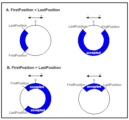
If SET, only use the window (defined in 'First Position' and 'Last Position' parameters) to accept trigger events. Positions outside the window are rejected and the external position latch is automatically newly activated. Only if the recorded position lies inside the window does Done become TRUE. In the case of absolute value positions there is exactly one window. In the case of modulo value positions the window repeats itself within the modulo cycle defined in the axis parameters (e.g. 0 to 360 degrees). |
|
E |
First Position |
Start position from where (positive direction) trigger events are accepted. Value included in window. If 'Window Only' parameter is OFF, this parameter is ignored |
|
F |
Last Position |
Stop position of the window. Value included in window. If 'Window Only' parameter is OFF, this parameter is ignored |
|
G |
Done |
Bit: turns ON Trigger event recorded |
|
H |
Busy |
Bit: when ON, the FB is not finished and new output values are to be expected |
|
I |
Command Aborted |
Bit: When ON, the FB has been aborted by MC Abort Trigger |
|
J |
Error bit |
Turns ON when an error occurs within the function block |
|
K |
Error ID |
The value indicates the error code. |
|
L |
Recorded Position |
Position where trigger event occurred |
This Function Block interrupts a measuring probe cycle initiated by MC_TouchProbe. MC_TouchProbe initiates a measuring probe cycle by activating a position latch in external encoder or drive hardware. If the process is to be terminated before the trigger signal has activated the position latch, MC_AbortTrigger can be used for this purpose.
|
|
Parameter Name |
Purpose |
|
A |
Axis |
Select the Axis you want to control. |
|
B |
Trigger Input |
Click to select the MC TriggerRef blockMC TriggerRef block.
|
|
C |
Execute |
Rising Edge triggers the FB and aborts the trigger event. |
|
D |
Done |
Bit: When ON, Trigger Event has been aborted |
|
E |
Busy |
Bit: when ON, the FB is not finished and new output values are to be expected |
|
F |
Error bit |
Turns ON when an error occurs within the function block |
|
G |
Error ID |
The value indicates the error code. |
This Function Block commands a never-ending controlled motion at a specified velocity.
|
|
|
|
Parameter Name |
Purpose |
|
A |
Axis |
Select the Axis you want to control |
|
B |
Execute |
Rising Edge Triggers FB |
|
C |
Continuous Update |
If Set, Input parameters are evaluated at each cycle |
|
D |
Velocity |
Value of the maximum ‘Velocity’ (not necessarily reached) [u/s]. |
|
E |
Acceleration |
Value of the ‘Acceleration’ (always positive) (increasing energy of the motor) [u/s2] |
|
F |
Deceleration |
Value of the ‘Deceleration’ (always positive) (decreasing energy of the motor) [u/s2].
|
|
G |
Jerk |
Value of the ‘Jerk’ [u/s3]. (always positive). Relevant only if S-curve profile has been selected in the Axis parameters Axis> Dynamics>Motion>Motion Profile; if S-curve has not been selected, this is ignored.Relevant only if S-curve profile has been selected in the Axis parameters Axis> Dynamics>Motion>Motion Profile; if S-curve has not been selected, this is ignored.
|
|
H |
Direction |
enum values: 0: mcPositiveDirection, (1: mcShortestWay -not applicable), 2: mcNegativedirection, 3:mcCurrentDirection. |
|
I |
Buffer Mode |
Buffer Mode is relevant only for Cyclic or Virtual Axis. Note that all buffered commands will be aborted if the applicable axis moves to the state ‘ErrorStop’. Any subsequent commands will be rejected. Buffer values |
|
J |
Done |
Bit: turns ON when Axis has reached the commanded veolcity |
|
K |
Busy |
Bit: when ON, the FB has control over the Axis |
|
L |
Active |
FB is currently controlling the axis |
|
M |
Command Aborted |
Bit: When ON, the FB has been aborted by another command |
|
N |
Error bit |
Turns ON when an error occurs within the function block |
|
O |
Error ID |
The value indicates the error code. |
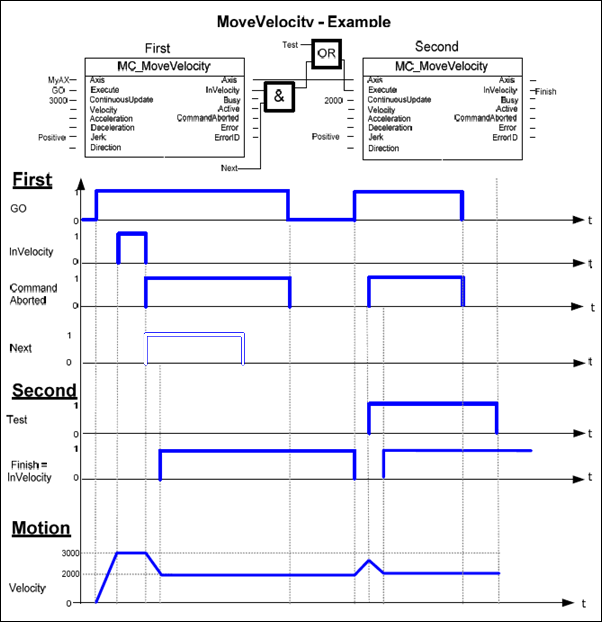
The following figure shows two examples of the combination of two MC_MoveVelocity Function Blocks:
The left part of the timing diagram illustrates the case if the Second FB is called after the First one is completed. If First reaches the commanded velocity 3000 then the output ‘First.InVelocity’ AND the signal next causes the Second FB to move to the velocity 2000.
In the next cycle ‘First.InVelocity’ is Reset and ‘First.CommandAborted’ is Set. Therefore the ‘Execute’ of the 2nd FB is Reset.
As soon as the axis reaches ‘Velocity’ 2000 the ‘Second.InVelocity’ is set.
The right part of the timing diagram illustrates the case if the Second move Function Block starts the execution while the First FB is not yet ‘InVelocity’.
The following sequence is shown: The First motion is started again by GO at the input ‘First.Execute’.
While the First FB is still accelerating to reach the velocity 3000 the First FB will be interrupted and aborted because the Test signal starts the Run of the Second FB.
Now the Second FB runs and decelerates the velocity to 2000.
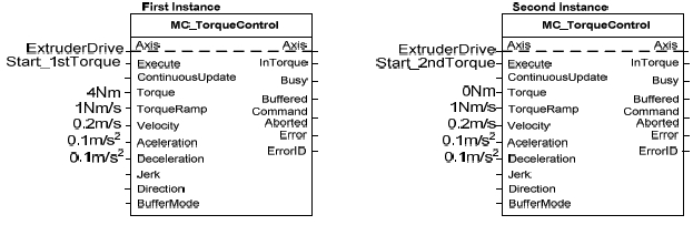
This Function Block continuously exerts a torque or force of the specified magnitude. This magnitude is approached using a defined ramp (‘TorqueRamp’), and the Function Block sets the ‘InTorque’ output if the commanded torque level is reached. This function block is applicable for force and torque. When there is no external load, force is applicable. Positive torque is in the positive direction of velocity.
|
|
|
|
Parameter Name |
Purpose |
|
A |
Axis |
Select the Axis you want to control |
|
B |
Execute |
Rising Edge Triggers FB |
|
C |
Continuous Update |
If Set, Input parameters are evaluated at each cycle |
|
D |
Torque |
Value of the torque (Torque or force in technical unit [u]). Thousandths of related torque |
|
E |
Torque Ramp |
The maximum time derivative of the set value of the torque or force (in technical unit per sec. [u/s]) |
|
F |
Direction |
enum values: 0: mcPositiveDirection, (1: mcShortestWay -not applicable), 2: mcNegativedirection, 3:mcCurrentDirection. |
|
G |
In Torque |
Setpoint value of torque or force equals the commanded value |
|
H |
Busy |
Bit: when ON, the FB has control over the Axis |
|
I |
Active |
FB is currently controlling the axis |
|
J |
Command Aborted |
Bit: When ON, the FB has been aborted by another command |
|
K |
Error bit |
Turns ON when an error occurs within the function block |
|
L |
Error ID |
The value indicates the error code. |
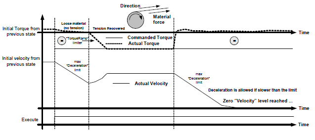
The example below shows the typical behavior of an intermediate “resistive” load (see ‘Deceleration’ limit) with some “inertia” (see ‘TorqueRamp’ limit).
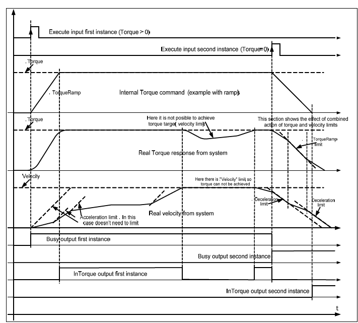
This example could be implemented in a Function Block Diagram like:
The second example (below) opposite signs for ‘Direction’ & ‘Torque’ are used (e.g. Retention or brake control). (In the FB: +Direction –Torque). It is like an unwinding application with torque on the material, and a break in the material. When the material breaks, as shown in the middle of the picture, this causes a drop in the real Torque value (in absolute terms): the velocity will decrease, limited by the fastest “deceleration” limit specified by the ‘Deceleration’ VAR_INPUT down to zero velocity (with no tension there is a risk of having shock breakings, so we have to limit to the fastest). In this case the torque setpoint might not be achieved.
|
|
This Function Block enables you to set Torque and apply it according to the physical values you define in the Axis Configuration, regardless of the motor specification.
The function continuously monitors the actual torque and ramps it up to a specified magnitude. This magnitude is approached using a defined ramp (‘Torque Ramp’), and the Function Block sets the ‘InTorque’ output if the commanded torque level is reached. Positive torque is in the positive direction of velocity.
|
|
|
|
Parameter Name |
Purpose |
|
A |
Axis |
Select the Axis you want to control |
|
B |
Execute |
Rising Edge Triggers FB |
|
C |
Continuous Update |
If Set, Input parameters are evaluated at each cycle |
|
D |
Torque |
Units defined in Axis Configuration |
|
E |
Torque Ramp |
Units defined in Axis Configuration, torque per sec. |
|
F |
Direction |
enum values: 0: mcPositiveDirection, (1: mcShortestWay -not applicable), 2: mcNegativedirection, 3:mcCurrentDirection. |
|
G |
In Torque |
Setpoint value of torque equals the commanded value |
|
H |
Commanded Torque |
This is the actual Torque value sent to the drive. |
|
I |
Actual Torque |
This is the actual torque, according to the units defined in the Axis configuration |
|
J |
Busy |
Bit: when ON, the FB has control over the Axis |
|
K |
Active |
FB is currently controlling the axis |
|
L |
Command Aborted |
Bit: When ON, the FB has been aborted by another command |
|
M |
Error bit |
Turns ON when an error occurs within the function block |
|
N |
Error ID |
The value indicates the error code. |
|
MC_ApplyForce can only be used with an axis defined with a linear actuator. |
This Function Block enables you to set Force and apply it according to the physical values you define in the Axis Configuration, regardless of the motor specification.
The function continuously monitors the actual force and ramps it up to a specified magnitude. This magnitude is approached using a defined ramp (Force Ramp’), and the Function Block sets the ‘InForce’ output if the commanded torque level is reached. Positive torque is in the positive direction of velocity.
Force can be applied when there is no external load, force is applicable. Positive force is in the positive direction of velocity.
|
|
|
|
Parameter Name |
Purpose |
|
A |
Axis |
Select the Axis you want to control |
|
B |
Execute |
Rising Edge Triggers FB |
|
C |
Continuous Update |
If Set, Input parameters are evaluated at each cycle |
|
D |
Force |
Units defined in Axis Configuration |
|
E |
Force Ramp |
Units defined in Axis Configuration, torque per sec. |
|
F |
Direction |
enum values: 0: mcPositiveDirection, (1: mcShortestWay -not applicable), 2: mcNegativedirection, 3:mcCurrentDirection. |
|
G |
In Force |
Setpoint value of force equals the commanded value |
|
H |
Commanded Force |
This is the actual Force value sent to the drive. |
|
I |
Actual Force |
This is the actual Force, according to the units defined in the Axis configuration |
|
J |
Busy |
Bit: when ON, the FB has control over the Axis |
|
K |
Active |
FB is currently controlling the axis |
|
L |
Command Aborted |
Bit: When ON, the FB has been aborted by another command |
|
M |
Error bit |
Turns ON when an error occurs within the function block |
|
N |
Error ID |
The value indicates the error code. |
This Function Block shifts the coordinate system of an axis by manipulating both the set-point position as well as the actual position of an axis with the same value without any movement caused. (Re-calibration with same following error).
|
|
|
|
Parameter Name |
Purpose |
|
A |
Axis |
Select the Axis you want to control |
|
B |
Execute |
Rising Edge Triggers FB |
|
C |
Position |
Position unit [u] (Means ‘Distance’ if ‘Relative’= TRUE) |
|
D |
Relative |
0: actual position value of the axis is set to the value of 'Position' parameter 1: 'Position' parameter is added to current position at the time FB started |
|
E |
Done |
Bit: turns ON when Axis has reached position |
|
F |
Busy |
Bit: when ON, the FB has control over the Axis |
|
G |
Error bit |
Turns ON when an error occurs within the function block |
|
H |
Error ID |
The value indicates the error code. |
This Function Block makes the transition from the state ‘ErrorStop’ to ‘Standstill’ or ‘Disabled’ by resetting all internal axis-related errors – it does not affect the output of the FB instances.
|
|
|
|
Parameter Name |
Purpose |
|
A |
Axis |
Select the Axis you want to control |
|
B |
Execute |
Rising Edge Triggers FB |
|
C |
Done |
Bit: turns ON when Axis has reached position |
|
D |
Busy |
Bit: when ON, the FB has control over the Axis |
|
E |
Error bit |
Turns ON when an error occurs within the function block |
|
F |
Error ID |
The value indicates the error code. |
This Function Block is not PLCopen-defined; it is a feature added by Unitronics.
|
|
|
|
Parameter Name |
Purpose |
|
A |
Axis |
Select the Axis you want to control |
|
B |
Jog Forward |
Rising Edge Triggers Jog Forward |
|
C |
Jog Backward |
Rising Edge Triggers Jog Backward |
|
D |
Velocity |
Value of the maximum ‘Velocity’ (not necessarily reached) [u/s]. |
|
E |
Acceleration |
Value of the ‘Acceleration’ (always positive) (increasing energy of the motor) [u/s2] |
|
F |
Deceleration |
Value of the ‘Deceleration’ (al+ways positive) (decreasing energy of the motor) [u/s2]. |
|
G |
Jerk |
Value of the ‘Jerk’ [u/s3]. (always positive). Relevant only if S-curve profile has been selected in the Axis parameters Axis> Dynamics>Motion>Motion Profile; if S-curve has not been selected, this is ignored.Relevant only if S-curve profile has been selected in the Axis parameters Axis> Dynamics>Motion>Motion Profile; if S-curve has not been selected, this is ignored.
|
|
H |
Done |
If currently jogging : velocity reached. Else : velocity is 0 |
|
I |
Busy |
Bit: when ON, the FB has control over the Axis |
|
J |
Command Aborted |
Bit: When ON, the FB has been aborted by another command |
|
K |
Error bit |
Turns ON when an error occurs within the function block |
|
L |
Error ID |
The value indicates the error code. |
This FB returns the value of a specific parameter according to the Parameter ID number.
It activates at the rising edge of the Enable bit.
|
|
|
Parameter Name |
Purpose |
|
A |
Axis |
Select the Axis you want to power |
|
B |
Enable |
When ON, power is being supplied to the drive that the Axis is linked to |
|
C |
Parameter number |
Use this tag to supply the parameter to read |
|
D |
A Valid set of outputs is available |
If true, a valid set of outputs is available for the FB |
|
E |
Busy |
FB is currently 'reading' |
|
F |
Error bit |
Turns ON when an error occurs within the function block |
|
G |
Error ID |
The value indicates the error code. |
This FB writes a value to a specific parameter according to the Parameter ID number.
It activates at the rising edge of the Enable bit.
|
|
|
|
Parameter Name |
Purpose |
|
A |
Axis |
Select the Axis you want to power |
|
B |
Execute |
Rising Edge Triggers FB |
|
C |
Parameter number |
Use this tag to supply the parameter to write to |
|
D |
Done |
Parameter value was written |
|
E |
Busy |
FB is currently 'writing' |
|
F |
Error bit |
Turns ON when an error occurs within the function block |
|
G |
Error ID |
The value indicates the error code. |