Method 1: Using negative limit switch and zero impulse evaluation
A:When homing mode is enabled, If negative limit switch N-OT=0, the drive first moves relatively quick into the negative direction until it reaches the negative limit switch. This is displayed in the diagram by the rising edge. Afterwards the drive slowly returns, and stops until reaches the falling edge.
B: When homing mode is enabled, If negative limit switch N-OT=1, the drive first moves slowly into the positive direction until reaches the falling edge.
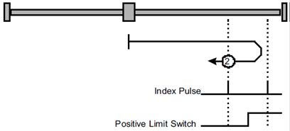
Method 2: Using positive limit switch and zero impulse evaluation
A:When homing mode is enabled, If positive limit switch P-OT=0, the drive first moves relatively quick into the positive direction until it reaches the positive limit switch. This is displayed in the diagram by the rising edge. Afterwards the drive slowly returns, and stops until reaches the falling edge.
B: When homing mode is enabled, If positive limit switch P-OT=1, the drive first moves slowly into the negative direction until reaches the falling edge.
Methods 3 and 4: Using positive reference switch and zero impulse evaluation
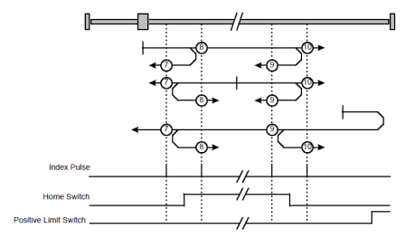
Methods 3 A:When homing mode is enabled, If positive reference switch H-S=0, the drive first moves relatively quick into the positive direction until it reaches the positive reference switch. This is displayed in the diagram by the rising edge. Afterwards the drive slowly returns, and stops until reaches the falling edge.
Methods 3 B: When homing mode is enabled, If positive reference switch H-S =1, the drive first moves slowly into the negative direction until reaches the falling edge.
Methods 4 A:When homing mode is enabled, If positive reference switch H-S =0, the drive first moves slowly into the positive direction until reaches the rising edge.
Methods 4 B:When homing mode is enabled, If positive reference switch H-S=1, the drive first moves relatively quick into the negative direction until it reaches the positive reference switch. This is displayed in the diagram by the falling edge. Afterwards the drive slowly returns, and stops until reaches the rising edge.
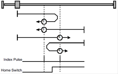
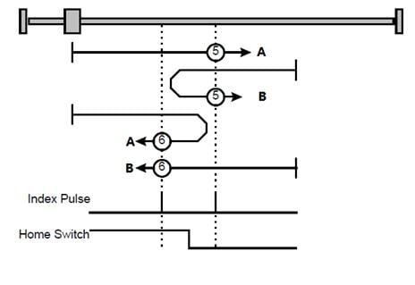
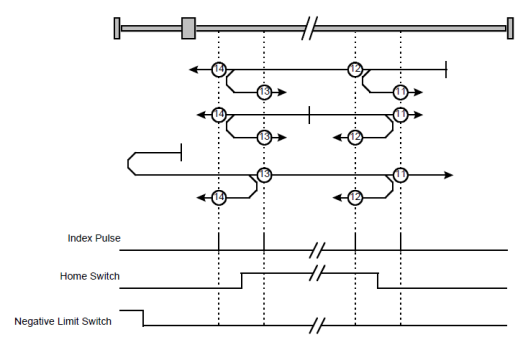
Methods 5 and 6: Using negative reference switch and zero impulse evaluation
Methods 5 A:When homing mode is enabled, If negative reference switch H-S =1, the drive first moves slowly into the positive direction until reaches the zero impulse evaluation. This is displayed in the diagram by the falling edge of H-S.
Methods 5 B: When homing mode is enabled, If negative reference switch H-S=0, the drive first moves relatively quick into the negative direction until it reaches the negative reference switch This is displayed in the diagram by the rising edge. Afterwards the drive slowly returns, and stops until reaches the zero impulse evaluation. This is displayed in the diagram by the falling edge of H-S.
Methods 6 A:When homing mode is enabled, If negative reference switch H-S=1, the drive first moves relatively quick into the positive direction until it reaches the negative reference switch. This is displayed in the diagram by the falling edge. Afterwards the drive slowly returns, and stops until reaches the zero impulse evaluation. This is displayed in the diagram by the rising edge of H-S.
Methods 6 B:When homing mode is enabled, If negative reference switch H-S =0, the drive first moves slowly into the positive direction, and stops until reaches the zero impulse evaluation. This is displayed in the diagram by the rising edge of H-S.
Methods 7 ~ 14 Using reference switch, limit switch and zero impulse evaluation
Methods 7~14 use the reference switch which is only active over parts of the distance.
Use positive limit switch P-OT
If this method 7~10 is used the drive first moves relatively quick into the positive direction
Methods 7A:When homing mode is enabled, If reference switch H-S=0, the drive first moves relatively quick into the positive direction, not reaches positive limit switch, until it reaches the reference switch H-S. This is displayed in the diagram by the rising edge. Afterwards the drive slowly returns, and stops until reaches the falling edge.
Methods 7B: When homing mode is enabled, If reference switch H-S=1, the drive first moves slowly into the negative direction until reaches the falling edge.
Methods 7C:When homing mode is enabled, If reference switch H-S=0, the drive first moves relatively quick into the positive direction , and reaches positive limit switch .The drive moves quickly into the negative direction. When reaching the rising edge of H-S ,the drive moves slowly , and moves into the negative direction until reaches the falling edge of H-S.
Methods 8 A:When homing mode is enabled, If reference switch H-S=0, the drive first moves relatively quick into the positive direction ,not reaches positive limit switch , Afterwards the drive moves slowly into positive direction when reaches the rising edge of H-S, and stops until reaches the zero impulse evaluation.
Methods 8 B: When homing mode is enabled, If reference switch H-S=1, the drive first moves slowly into the negative direction until reaches the falling edge of H-S. Then moves slowly into the positive direction, stops until reaches the zero impulse evaluation. This is displayed in the diagram by the H-S rising edge.
Methods 8 C:When homing mode is enabled, If reference switch H-S=0, the drive first moves relatively quick into the positive direction ,reaches positive limit switch ,Afterwards the drive moves quickly into the negative direction, until reaches the rising edge of H-S. The drive slows down, and moves into the negative direction. Reaches the falling edge of H-S, the drive returns into positive direction, until reaches the zero impulse evaluation. This is displayed in the diagram by the H-S rising edge.
Methods 9 A:When homing mode is enabled, If reference switch H-S=0, the drive first moves relatively quick into the positive direction, not reaches positive limit switch. Afterwards the drive moves slowly into positive direction when reaches the rising edge of H-S. The drive slows down to stop until reaches the falling edge of H-S. Then drive returns slowly, and stops until reaches the zero impulse evaluation. This is displayed in the diagram by the H-S rising edge.
Methods 9 B: When homing mode is enabled, If reference switch H-S=1, the drive first moves slowly into the positive direction until reaches the falling edge of H-S. Then moves slowly into the negative direction, stops until reaches the zero impulse evaluation. This is displayed in the diagram by the H-S rising edge.
Methods 9 C:When homing mode is enabled, If reference switch H-S=0, the drive first moves relatively quick into the positive direction ,reaches positive limit switch ,Afterwards the drive moves quickly into the negative direction ,until reaches the rising edge of H-S. The drive slows down, and moves into the negative direction, and stops until reaches the zero impulse evaluation.
Methods 10 A:When homing mode is enabled, If reference switch H-S=0, the drive first moves relatively quick into the positive direction, not reaches positive limit switch. Afterwards the drive moves slowly into positive direction when reaches the rising edge of H-S. If reaches the falling edge of H-S, the drive moves slowly into positive direction until reaches the zero impulse evaluation.
Methods 10 B: When homing mode is enabled, If reference switch H-S=1, the drive first moves slowly into the positive direction until reaches the zero impulse evaluation. This is displayed in the diagram by the H-S falling edge.
Methods 10 C:When homing mode is enabled, If reference switch H-S=0, the drive first moves relatively quick into the positive direction ,reaches positive limit switch ,Afterwards the drive moves quickly into the negative direction, until reaches the rising edge of H-S. The drive slows down to stop. Then the drive returns slowly to the positive direction, stops until reaches the zero impulse evaluation. This is displayed in the diagram by the H-S falling edge.
1. Use negative limit switch
If this method 11~14 is almost same as method 7~10, the drive first moves relatively quick into the negative direction.
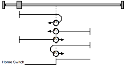
Method 17~20, 23~30: Homing operation to the negative limit switch
If this method is used the drive first moves relatively quick into the negative direction, until it reaches the negative limit switch. This is displayed in the diagram by the rising edge. Afterwards the drive slowly returns and searches for the exact position of the limit switch. The zero position refers to the descending edge from the negative limit switch.
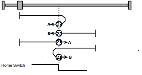
Methods 21,22 Using reference switch
Methods 21 A:When homing mode is enabled, If reference switch H-S =1, the drive first moves slowly into the positive direction until reaches the falling edge of H-S.
Methods 21 B: When homing mode is enabled, If reference switch H-S=0, the drive first moves relatively quick into the negative direction until it reaches the reference switch this is displayed in the diagram by the rising edge. Then the drive returns slowly to the positive direction, stops until reaches the falling edge of the H-S.
Methods 22 A:When homing mode is enabled, If reference switch H-S=1, the drive first moves relatively quick into the positive direction until it reaches the reference switch. This is displayed in the diagram by the falling edge. Afterwards the drive slowly returns, and stops until reaches the rising edge of the H-S.
Methods 22 B:When homing mode is enabled, If reference switch H-S =0, the drive first moves slowly into the negative direction until reaches the rising edge of the H-S.
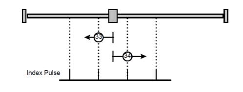
Methods 33,34 Using zero impulse evaluation
Methods 33:The drive moves slowly into the negative direction,stops until reaches the zero impulse evaluation.
Methods 34:The drive moves slowly into the positive direction,stops until reaches the zero impulse evaluation.
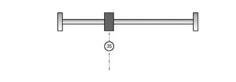
Method 35: Set current position as the homing point
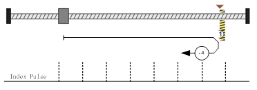
Method -4 Movement in positive direction, hitting an end and reversing to travel,the target homing position is the first C pulse
In this method, the motor moves in positive direction. When it hits an end so that the torque set in Pn207 is reached for the blocking time set in Pn208, movement in the opposite direction, and the target homing position is the first C pulse.
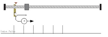
Method -3 Movement in negative direction, hitting an end and reversing to travel,the target homing position is the first C pulse
In this method, the motor moves in negative direction. When it hits an end so that the torque set in Pn207 is reached for the blocking time set in Pn208, movement in the opposite direction, and the target homing position is the first C pulse.
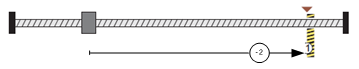
Method -2: Movement in positive direction, hitting an end, makes the current position for the origin.
In this method, the motor moves in positive direction. When the drive hits an end so that the torque set in Pn207 is reached for the blocking time set in Pn208, and makes the current position for the origin.
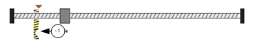
Method -1:Movement in negative direction, hitting an end, makes the current position for the origin.
In this method, the motor moves in negative direction. When the drive hits an end so that the torque set in Pn207 is reached for the blocking time set in Pn208,and makes the current position for the origin.
Notes: When starting homing on homing method about input signal, the rotation direction of servo motor is associated with the initial status of the input signal.
Changing the initial status by inverse input on set Pn516/Pn517 if it is necessary. When using reference switch homing/O should be set as Pn509/Pn510.