You add axes according to the physical structure of your system. At the same time, you define the mechanical properties of your system, modifying the default values as described in this section.
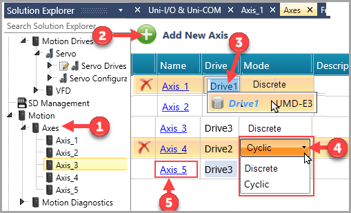
In the Solution Explorer, click Motion>Axes.
Click Add New Axis; note the pop-up will offer you the option to import Ready-made Motion code; you may do this now or later by right clicking Motion in the Solution Explorer.
UniLogic adds an axis.
Note the option to add a virtual axis.
Click Drive and select your drive.
Click Mode to select Discrete or Cyclic.
Note that Cyclic is intended for use with EtherCAT Multi-Axes functions.
Click the Axis to open its Configuration.
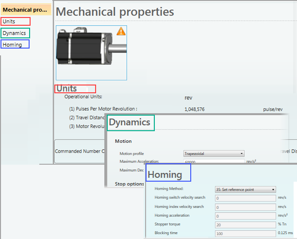
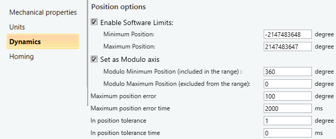
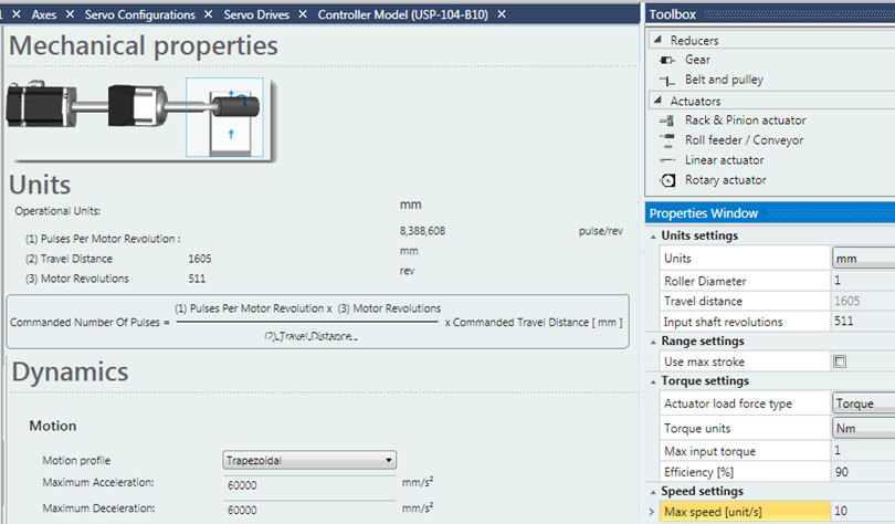
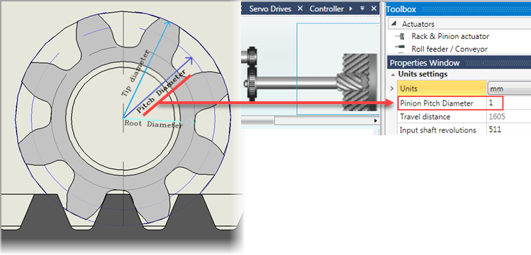
The Configuration is organized into groups.
Click a group - Mechanical properties, Units, Dynamics, Homing - to view and edit its parameters.
Note that selecting Dynamics> Enable Software Limits allows limits to be set via program; for example, via HMI screen. Dynamics> Enable Software Limits allows limits to be set via program; for example, via HMI screen. You can also set the axis to function as a modulo axisYou can also set the axis to function as a modulo axis..
If enabled, monitor via struct: Global>Axis>Status>Bit 10 (Position: Software Limits Exceeded).
This bit turns ON whenever the axis position is not within the limits you have set in Software.
In order to see the direction and number of units exceeded, monitor the parameter Actual Position with the FB MC Read.
Note that if limits set in your hardware limits are exceeded, the drive will stop and POT or NOT will be displayed on the drive's display. Check Global>Axis>Emergency code to see the direction:
- POT (Positive Over Travel) =34433
- NOT (Negative Over Travel) =34434
Homing
Information regarding Homing Methods may be found in the topic Axis Homing Methods
The Toolbox on the right displays Reducers and Actuators; double-click or drag your selection to place it next to the UMD.
Note that the Properties Window shows the parameters of the device you select.
Units settings
The Units parameter enables you to select the unit of torque or force.
|
You can set system limits either as 0.1% of motor rated torque or using physical values:
Note that the values calculated automatically by UniLogic may differ from the actual system values, due to variable functioning of mechanical components, for example, friction may be affected by ambient temperature, motor's oil seal friction value etc. |
Click on the drop-down to reveal the options. The units you select, and the values you enter are used by UniLogic to calculate travel distance per input shaft revolution as shown in the next two images.
Note that linear actuators also offer Custom Units. Custom Units are for display purposes only, and may not be converted.
|
Rack & pinion and Roll/Conveyor actuators Allow you to convert rotary movement to linear values. Note that the values are calculated using pi; the higher the number of input shaft revolutions, the more accurate the calculations. |
Rack and Pinion Actuator
Pinion Pitch Diameter may also be referred to as Diametral Pitch, or as the Reference Diameter.
When you set the pinion effective diameter and the units, UniLogic calculates the lowest common value, and displays the Travel Distance results per Input Shaft Revolutions according to the units selected (mm, cm, In, etc).
Roll Feeder / Conveyor
Set the roller diameter and the units, UniLogic calculates the Travel Distance per Input Shaft Revolutions according to the units selected.