A single UniStream can be defined and function simultaneously as a master or slave, and may also contain multiple slave definitions.
UniLogic enables you to easily implement MODBUS communications by configuration rather than programming.
Most application requirements are met by Periodic operations, which run according to the time intervals you set.
You can also run Aperiodic operations. You can trigger a single operation, or a group of operations, via your application.
This means that an application might:
Use simple Periodic Operations to read/write data from/to many sensors,
Use an Aperiodic Operation to write a single set-point as the result of a run-time condition,
Use an Aperiodic Operation to turn a group of outputs ON as the result of a run-time condition.
|
A single UniStream can be defined and function simultaneously as a master or slave, and may also contain multiple slave definitions. |
|
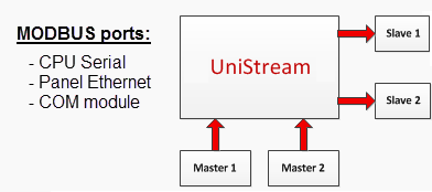
MODBUS may run via ports on the UniStream CPU, HMI panel, or COM modules.
CPU RS485 Port
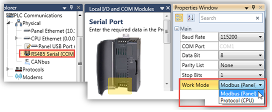
On the Solution Explorer, select PLC Communications>Physical> RS485 Serial (COM1) and edit the parameters in the Properties Window as required.
Under Work Mode, select MODBUS (Panel).
|
Note that for PLC Controllers, the Serial COM struct countersSerial COM struct counters are only active when the COM Port is assigned to Tx/Rx or VFD.
When the COM Port is configured as Modbus Panel, use the Remote Slave struct to monitor the communication status for each individual slave. |
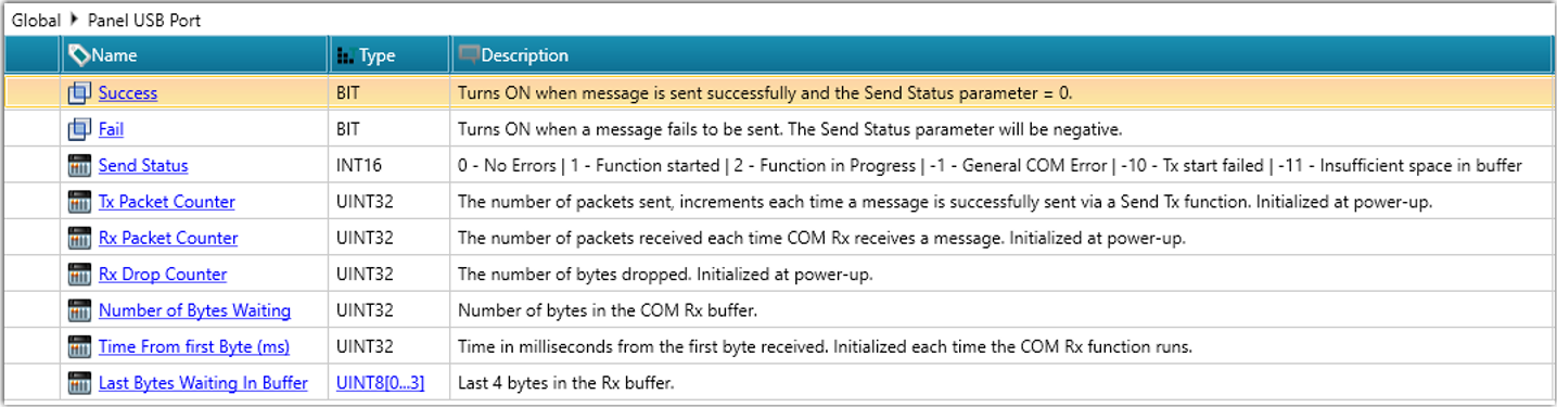
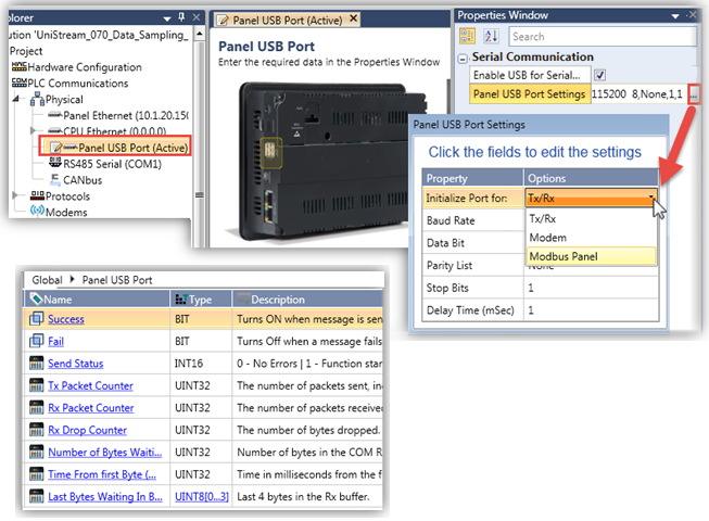
Panel USB port
Select Enable USB for Serial Device, click USB Port Settings, then click Initialize Port for: and select the desired communication type.
Note that enabling the port automatically adds the Panel USB Port struct to use in your program.
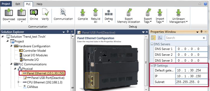
On the Solution Explorer, select PLC Communications>physical> Panel Ethernet and edit the parameters in the Properties Window as required.
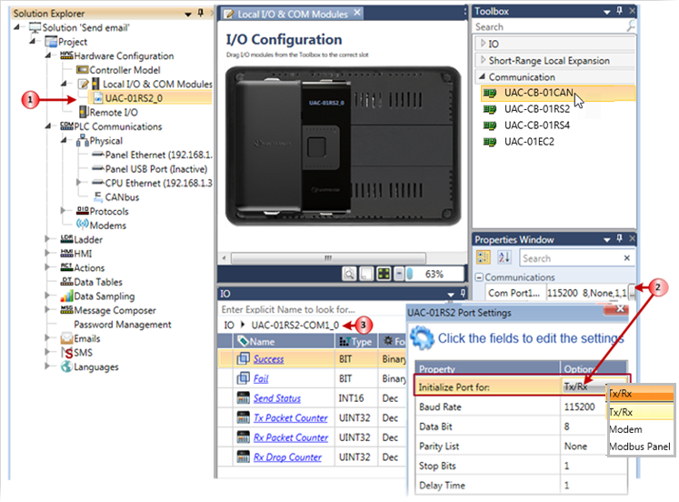
To run MODBUS serial communications through a COM module port, select MODBUS Panel in the port settings.
Note: In PLC Controllers, the Remote Slave struct is used to monitor the communication status of each slave.
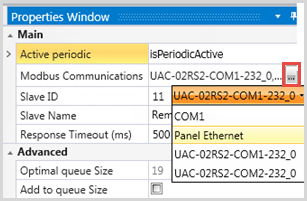
On the Solution Explorer tree, click PLC Communications to expand it, then Protocols > MODBUS > Master; this opens the MODBUS ports.
Select the desired port, and click Add new Remote Slave.
You can also add Remote Slaves by right-clicking a MODBUS port in the Explorer tree
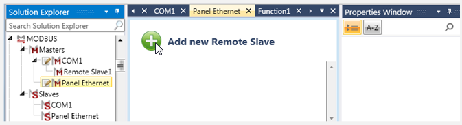
The remote slave's Properties Window opens on the right of the screen, as does Add New Operation in the center.
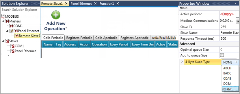
Set the remote slave definitions in the Properties Windowremote slave definitions in the Properties Window.
|
MODBUS Slave Properties Window Parameters |
|
|
Active periodic |
This bit controls, for this particular slave, whether Periodic Operations run or not. Turn it ON to run the Coil and Register Periodic operations according to the time interval you have set in the individual operation. Turn it OFF to suspend all Periodic operations for this slave. |
|
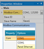
Modbus Communications |
Use this to select the port for the MODBUS operations by clicking the drop-down arrow.
|
|
Slave ID |
Enter the ID number of the slave to be accessed. The range is 1-255. |
|
Slave Name |
Assign a name to help you identify the slave |
|
Response Timeout (ms) |
The default is 500ms, click the field to edit the value. |
|
Advanced |
The Queue options may be used in certain programs that rely on large quantities of data. This is described in the section below, Dropped Operations. |
For each slave, add new operations as described below.
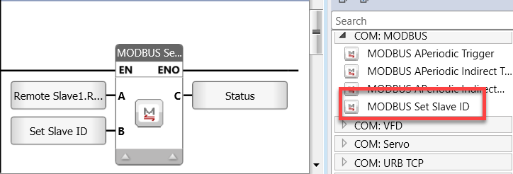
Setting the Serial Slave ID via Ladder
Note that you can change the Serial Slave ID at runtime via the MODBUS Ser Set Slave ID ladder function.
|
|
Parameter Name |
Purpose |
|
A |
Slave ID |
Select the Serial Slave whose ID you want to change |
|
B |
ID to set |
Link a tag or a constant to set the Serial Slave ID number |
|
C |
Status |
• 0 = Success |
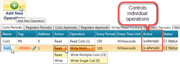
The MODBUS operations you create are arranged in a table. You can create both Period and Aperiodic operations.
To add a single operation:
Select the tab with the desired operation type, and click Add New Operation. UniLogic adds a row to the table.
Click in fields to edit and make selections.
The next image shows Periodic operations.
|
Note that while the Active Periodic setting in Properties determines whether the master will run operations periodically, you can prevent an individual operation from running. To do this, assign a bit to the operation's Active parameter. To prevent the operation from running, turn this bit OFF. |
The next image shows Aperiodic operations.
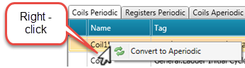
You can convert Periodic operations to Aperiodic, and vice versa. Note that you can also select several operands by holding down CTRL while clicking them and the right-clicking them.
|
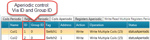
Note that the ID parameters allow you to use Aperiodic Ladder elements to run the operations via your program. |
Status
Link a tag to the Status field to contain the MODBUS Transaction Status.
The status codes are in the following table.
|
Error code |
Translation |
|
-11 |
Timeout |
|
-1 |
Unknown error |
|
-2 |
3-second temporary Slave Messaging Suspension, |
|
Modbus General Errors |
|
|
1 |
illegal function |
|
2 |
illegal data address |
|
3 |
illegal data value |
|
4 |
slave or server failure |
|
5 |
acknowledge |
|
6 |
slave or server busy |
|
7 |
negative acknowledge |
|
8 |
memory parity error |
|
10 |
gateway path unavailable |
|
11 |
target device failed to respond |
|
12 |
invalid crc |
|
13 |
invalid data |
|
16 |
too many data |
As you add/delete each Modbus operation, UniLogic increments/decrements their number.

Write/Read Multiple Registers - Periodic and Aperiodic
These operations perform a combination of one Read operation and one Write operation in a single MODBUS transaction.
The Write operation is performed before the Read. Holding registers are addressed starting at zero. (Holding Registers 1-16 are addressed in the PDU as 0-15.)
The request specifies:
The start address and the number of holding registers to be read
The start address, number of holding registers, and the data to be written.

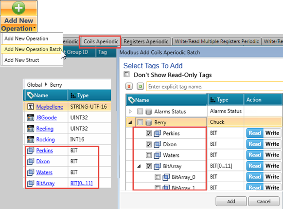
To add a batch of operations:
Select the tab with the desired operation type, and click the drop-down arrow under Add New Operation.
Select Add New Operation Batch; UniLogic opens the Add window, displaying the appropriate tag type.
View the tags within structs either via the Expand/Collapse icons next to the Search field, or by clicking arrows to expand them.
In the next image, Coils are selected, therefore only coils are displayed, including coils from within structs.
Check the tags you want, and click Add. In the struct shown below, a bit array is selected, along with two individual bits.
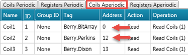
In the next image, note that the operation Coil1 address starts at zero, and Coil2 at 12. This allots sufficient space for for the bit array, 0-11.
In the next image, the Aperiodic tabs were selected when the struct was added.
The bit tags were automatically categorized into Aperiodic Coils, and the registers to Aperiodic registers.

Operation Parameters
You can select Periodic or Aperiodic operations. The parameters differ as listed in the next table.
|
Name |
Definition |
||||||||||||||||||||||||||||||||
|
Name |
Enter an identifying name for your convenience. |
||||||||||||||||||||||||||||||||
|
Tag |
Link to the tag containing the data for the operation
|
||||||||||||||||||||||||||||||||
|
Address |
This is the address in the slave device, and maps between it and the Tag. |
||||||||||||||||||||||||||||||||
|
Action |
Click to select the desired action (Read/Write) |
||||||||||||||||||||||||||||||||
|
Operation |
Click to select the MODBUS operation MODBUS operation. Read Operations UniStream acts as a master, accessing requested data in a remote device, and writing the data into a tag or buffer within UniStream.
Write Operations UniStream acts as a slave; a MODBUS master can access and write to specified tags within UniStream.
|
||||||||||||||||||||||||||||||||
|
Periodic Parameters: relevant for periodic operations |
|||||||||||||||||||||||||||||||||
|
Every Period Every Time Unit |
Determine the frequency of the periodic operation |
||||||||||||||||||||||||||||||||
|
Active |
Link a bit to control whether or not the individual operation will run. |
||||||||||||||||||||||||||||||||
|
APeriodic Parameters: relevant for aperiodic operations. Trigger via MODBUS Aperiodic Functions |
|||||||||||||||||||||||||||||||||
|
ID |
Use the ID number in your ladder application |
||||||||||||||||||||||||||||||||
|
Group ID |
Use the Group ID number in your ladder application. |
||||||||||||||||||||||||||||||||
|
Status |
Link a register to hold the status codestatus code. Modbus transaction status errors:
The actual message that the code indicates, is from the MODBUS protocol itself. Note that this must be reset by your application. |
||||||||||||||||||||||||||||||||
Defining a slave automatically creates a Remote Slave struct.
|
Name |
Data Type |
Definition |
|
|
Sessions |
UINT32 |
Total number of attempted sessions |
These are incremental counters that tracks the total number of events. They are reset at powerup. |
|
Success |
UINT32 |
Total number of successful sessions |
|
|
Fail |
UINT32 |
Total number of failed sessions |
|
|
MODBUS Slave Status |
UINT8 |
Status |
|
|
1 - No errors: the number of attempted sessions = the number of successful sessions 2 - No connections made (no sessions established) 3 - Connection exists, but there is an error in the MODBUS commands |
|||
|
Remote Slave ID |
UINT8 |
Read-only |
|
|
Port |
UINT16 |
Read-only |
|
|
IP |
UINT32 |
Read-only |
|
|
Dropped |
UINT32 |
Read-only. This is an incremental counter that tracks the total number of dropped sessions. It is reset at powerup. |
|
As mentioned previously, a single UniStream can function as both Master and as Slave.
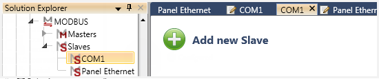
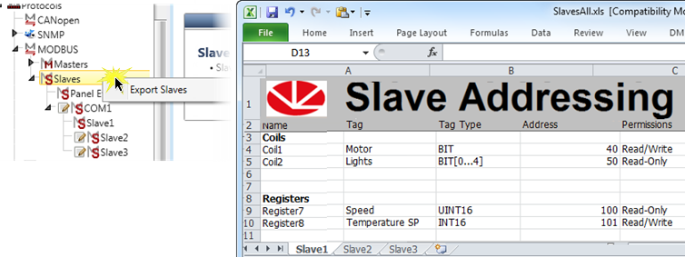
On the Solution Explorer tree, click PLC Communications to expand it, then Protocols > MODBUS > Slaves; this opens the MODBUS ports.
Select the desired port, and click Add new Slave.
You can also add slaves by right-clicking a MODBUS port in the Explorer tree
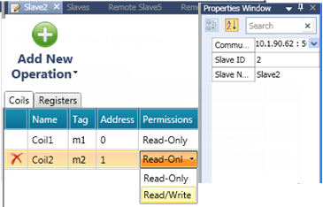
The slave's Properties Window opens on the right of the screen, as does Add New Operation in the center.
Set the slave definitions in the Properties Windowslave definitions in the Properties Window.
|
MODBUS Slave Properties Window Parameters |
|
|
Modbus Communications |
Use this to select the port for the MODBUS operations by clicking the drop-down arrow.
|
|
Slave ID |
Enter the ID number of the slave to be accessed. The range is 1-255. |
|
Slave Name |
Assign a name to help you identify the slave |
For each slave, add new operations as described below.
The MODBUS operations you create are arranged in a table.
To add a single operation:
Select the tab with the desired operation type, and click Add New Operation. UniLogic adds a row to the table.
Click in fields to edit and make selections. Note that Permissions determines master access to the slave for the operation.
To add a batch of operations:
Select the tab with the desired operation type, and click the drop-down arrow under Add New Operation.
Select Add New Operation Batch; UniLogic opens the Add window, displaying the appropriate tag type.
View the tags within structs either via the Expand/Collapse icons next to the Search field, or by clicking arrows to expand them.
In the next image, Coils are selected, therefore only coils are displayed, including coils from within structs.
Check the tags you want, and click Add. In the struct shown below, a bit array is selected, along with two individual bits.
To add a struct of operations:
Select the tab with the desired operation type, and click the drop-down arrow under Add New Operation.
Select Add New structs; UniLogic opens the Add window, displaying the structs.
Operation Parameters
|
Name |
Definition |
|
Name |
Enter an identifying name for your convenience. |
|
Tag |
Link to the tag containing the data for the operation
|
|
Address |
This is the address in the slave device, and maps between it and the Tag. |
|
Permissions |
Click to enable the desired access to the slave (Read/Write) |
Defining a slave automatically creates a Slave struct.
|
Name |
Data Type |
Definition |
|
|
Sessions |
UINT32 |
Total number of attempted sessions |
These are incremental counters that track the total number of events. They are reset at powerup. |
|
Success |
UINT32 |
Total number of successful sessions |
|
|
Fail |
UINT32 |
Total number of failed sessions |
|
|
Num of Clients |
UINT8 |
Read-only. This is the number of clients currently connected to the slave. |
|
|
Port |
UINT16 |
Read-only |
|
|
Slave ID |
UINT32 |
Read-only |
|
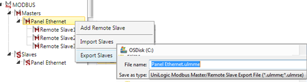
You can export and import a UniStream MODBUS Master's slave definitions, via a proprietary Unitronics file. To export the definitions of:
All slaves, right-click Slaves and select Export or Import Slaves.
A single slave, right-click the slave's name.
Local Slaves
You can export and import a UniStram MODBUS Local's slave definitions.
To export the definitions of:
All slaves to Excel, right-click Slaves and select Export Slaves Addressing to Excel.
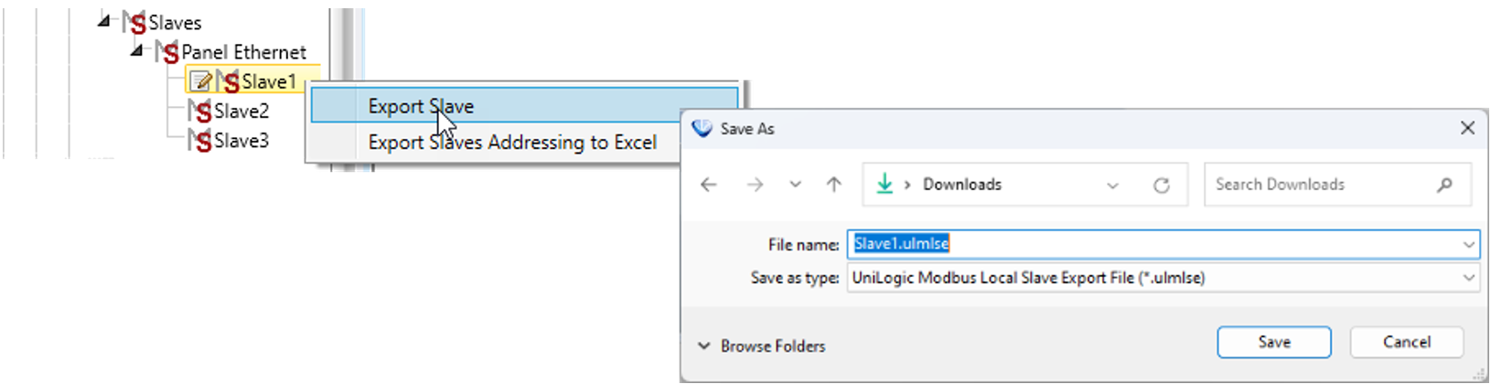
A single slave via a proprietary Unitronics file, right-click the Slave's name and select Export Slave.
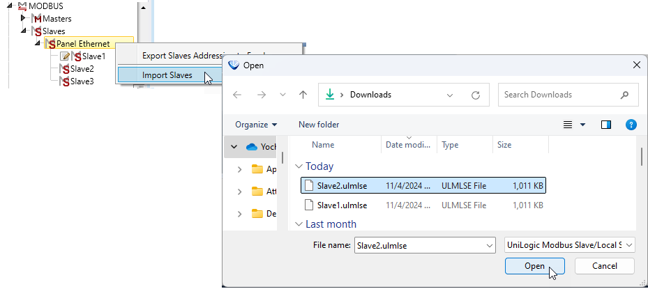
To import the definitions of all Local slaves, right-click the Local slave and select Import Slaves.
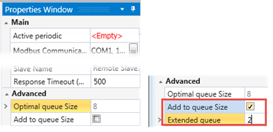
In certain cases, for example in a large project with a large number of sensors, the entire queue of operations may not be able to run during the scan. To see if this is the case, monitor the Drops parameter in the Remote Slave's struct, and see if there are dropped operations during the scan.
The Drops parameter is a continuously incrementing counter that cannot be reset by the user. To track the number of drops, store the value.
If so, first examine your application. Operations that only need to run occasionally during a scan, such as powering on a machine, can be run as Aperiodic operations via ladder.
If this does not remedy the problem, in the Properties window of the Remote Slave, check Add to queue Size, and enter a value under Extended queue.
Note that since this will increase the scan time, it is recommended to add in small increments of 2.
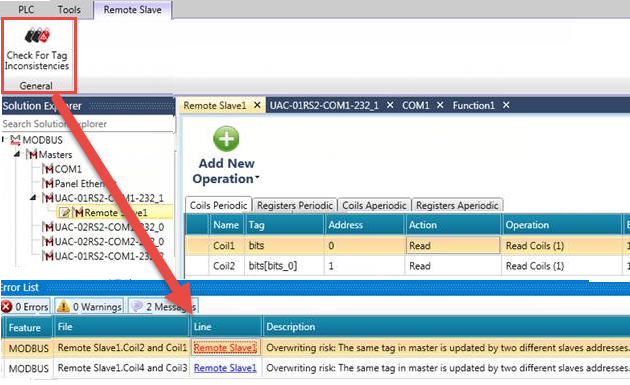
Remote Slave Address OverLap
You can select the ribbon tab Remote Slave while you are editing, and click it to check for address overlap. This can help you avoid unintentionally overwriting data.
If you are connected to the Internet, you can access this UniLogic tutorial: