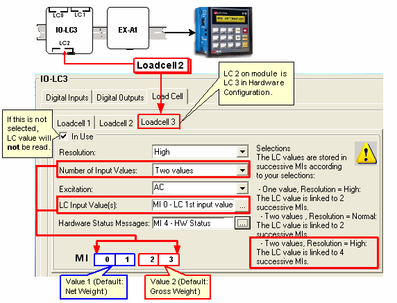
The IO-LCx Hardware Configuration enables you to configure a loadcell, plus the digital input and digital outputs located on the module. These digital I/Os enable you to implement setpoints that are processed within the I/O module, independently of the controller and its program scan, enabling a fast response to process events.
The number of Loadcell tabs in the Hardware Configuration window depends upon the loadcell module.

|
Parameter |
Type |
Function |
|
In use |
|
Select 'In Use' to enable the loadcell for the application. Note ♦ A loadcell marked 'in use' can be suspended according to application conditions via the Advanced Calibration function Enable/Disable loadcell. This may be done to shorten the application's calibration time. |
|
Resolution |
MI |
Selecting High enables you to link the input value to one or 2 MIs, Normal to an MI. Note that you can process 2 MIs values as 'long' integers as explained in the Help topic Special Function 'Long' Integers. |
|
LC Input Value(s) |
MI |
When the application runs, these registers contain the weight value input to the controller from the I/O LCx. The LC values are automatically linked to successive MIs according to the Number of Input Values and Resolution you select. Take care not to overwrite these MIs during the application. Selections:
The default representation mode for the first value is Net Weight, and Gross Weight for the second. |
|
Excitation |
|
AC is the default, recommended Excitation method. You may select the DC option if your application requires. |
|
Hardware |
MI |
Provides a bitmap showing the status of the module. |
|
Bit# |
Description |
Turns ON when: |
Turns OFF when: |
|
0 |
Scale motion |
Scale is in motion |
|
|
1 |
Input Value Range |
Input value is out of range
|
Input value is in range |
|
2 |
Input Value Validity
|
Input Value is invalid
|
Input Value is valid |
|
3 |
Loadcell Calibration Status |
When less than 2 points are calibrated |
At least 2 points are calibrated |
|
4 |
Input Power Supply Status |
No Power |
Power Supply OK |
|
|||
|
Note ♦ Bits 6 & 7 are linked to Outputs 0 & 1, located on the I/O module. Bit 6 is related to Output 0, Bit 7 to Output 1. Bits 6 & 7 can be used to monitor the setpoint output's status from within the Ladder application. The I/O module itself controls the setpoint function of the outputs. The module turns the outputs ON and OFF when the current loadcell input value reaches setpoint. Since the function is based in the firmware of the expansion module, when the output's status changes as a result of reaching/departing from setpoint, the status change is not registered by the Ladder application. Examples
|
|||
|
6 |
Setpoint Status, Output 0 |
Output 0 is ON |
Output 0 is OFF |
|
7 |
Setpoint Status, Output 1 |
Output 1 is ON |
Output 1 OFF |
|
SB91 |
I/O Exp. Module--Command buffer is full |
ON when commands cannot be sent to the I/O module. |
OFF when commands can be sent to the I/O module.. |