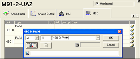
You can use certain outputs as High-speed Outputs (HSO) via PWM (Pulse Width Modulation).
The ratio of the "on" period of a cycle to the total cycle period. This value may be from 0-1000, and is expressed as a percentage.
If, for example, the constant 750 is stored into the Duty Cycle operand, the duty cycle is equal to 75.0% This means that the pulse will hold a positive state during 75.0% of the total cycle.
Note that F=1/T, where T is the duration time of a complete cycle. Frequency settings differ from npn to pnp output type.
npn: You can use a value of 0, or a value from 8-50000Hz ( 50kHz).
pnp: You can use a value of 0, or a value from 8-1500HZ.
Other frequency values are not supported.
Changes the operating mode of the output from normal output mode to HSO mode:
0 (SET)=Normal Mode, 1 (RESET): HSO Mode.
In the figure below, MI 22 Duty Cycle Value is equal to 250. This results in the duty cycle being 25% of the total cycle time.

|
Note ♦ |
If values out of range enter the Duty Cycle and Frequency operands, their values remain unchanged—the operands retain the last legal values stored. |
M90 OS versions 2.00 (B01) and later enable you to use the last on-board output of M90 models T1 and T1-CAN in either:
High Speed Output (HSO) mode
Normal output mode.
Using HSO mode gives you the ability to use an output as a PWM (Pulse Width Modulation) output. You can also use an output in HSO mode together with stepper motor controllers.
To use HSO mode:
Use System Integer SI 16 HSO Mode to change the operating mode of Output 11 from Normal mode to HSO mode: 0=Normal Mode, 1: HSO Mode.
This should be part of your program’s Power-up tasks.
Set the output frequency (F) by storing a value into SI 17 HSO Frequency.
Set the duty cycle—the ratio of the "on" period of a cycle to the total cycle period—by storing a value into SI 18 Duty Cycle.
Use SB 16 HSO RUN to control the output; when SB 16 is ON, Output 11 operates.
In the figure below, SI 18 is equal to 250. This results in the duty cycle being 25% of the total cycle time.

Note that:
If you store out-of-range values into SI 17 and SI 18, their values remain unchanged—they retain the last legal values stored.
Note 2. All parameters except SI 16 may be changed during run-time.
Open Hardware Configuration.
Click on the icon representing your controller model. The appropriate hardware model window opens.
Select the appropriate M91 model to display the model's I/O options.
Click on the High Speed Outputs tab, then select High Speed Output (PWM).

The Select Operand and Address box will open 3 times, enabling you to link MIs for Common Frequency & Duty Cycle, and MB for Enable Output.
|
Note ♦ |
The same MI sets Frequency for both outputs. |

The PWM output is now part of the configuration.
In order to implement PWM in compatible Jazz controllers, you use Special Functions (SI140) to change the function of the output from that of a normal digital output to PWM. Note that you must:
Check the technical specifications of your model to see if it supports PWM,
and which specific outputs support it.
Ensure that you are using the latest OS version.
Implementing PWM
The frequency value is fixed at 1.57Hz.
The duty cycle can be determined by the user – 0-100% (100%=1000)
In order to change the output function:
Store the value of the duty cycle to SI141: (legal values from -1 to 1000)
0 – 0%
1000 – 100%
Store the value that determines the output number to SI140 using the value 71x, where x=the output number.
To change the output function from PWM back to normal, store -1.
Example: for models JZ-10 T10/T17/T40 the relevant outputs are O0 and O1. To configure O0 to PWM, store 710 into SI40; and store 711 for O1 .
For models JZ-10 UN20/UA24, the relevant outputs are O5 and O6. To configure O5 to PWM, store 715, and store 716 for O6
Note that, in your program, you must first store the value to SI141, and then execute the function by storing the value to SI140.
Related Topics
Configuring a Thermocouple: M91 OPLC series
Analog input value--Out Of Range
High-Speed Counters, Shaft Encoders, Frequency Measurer