On this platform, CAN1 shares pins with I2C5. CAN1 is enabled by default.
I2C5 is reserved for M-core use and is not available from Linux.
You can use the CANbus port on the CPU or a CANbus add-on module to communicate:
with external devices via protocols such as CANopen
establish UniStream to UniStream communications via UniCAN
communicate with Remote I/Os via an EX-RC1 adapter
via virtually any devices via CANbus Layer 2
|
On this platform, CAN1 shares pins with I2C5. CAN1 is enabled by default. |
CANbus SpecificationsCANbus Specifications
|
Power Requirements: 24VDC ( ±4%), 40mA max. per unit |
|
|
Galvanic Isolation between CANbus and controller: Yes |
|
|
Baud rate |
Max. Network Cable Length: |
|
1 Mbit/s |
25 m |
|
500 Kbit/s |
100 m |
|
250 Kbit/s |
250 m |
|
125 Kbit/s |
500 m |
|
100 Kbit/s |
500 m |
|
50 Kbit/s |
1000 m |
|
20 Kbit/s |
1000 m |
|
Note |
Cable lengths over 500 meters require an additional power supply. |
|
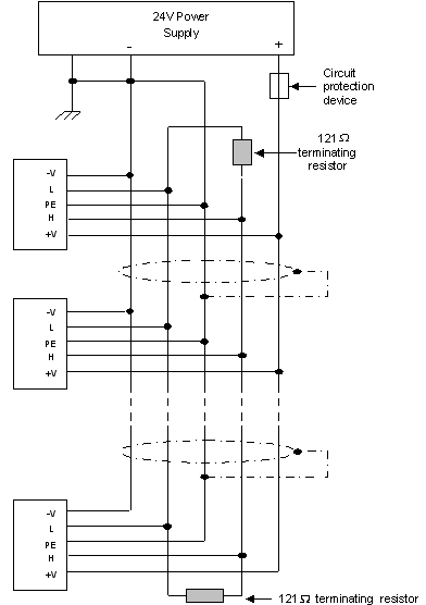
Wiring Considerations |
|
|
Use twisted-pair cable. DeviceNet® thick shielded twisted pair cable is recommended. |
|
|
Network terminators: These are supplied with the controller. Place terminators at each end of the CANbus network. Resistance must be set to 1%, 121Ω, 1/4W. |
|
|
Connect the ground signal to the earth at only one point, near the power supply. |
|
|
The network power supply need not be at the end of the network. |
|
|
Maximum number of controllers in a network: 63. |
|
CANbus Wiring DiagramCANbus Wiring Diagram
CANbus Setup StructCANbus Setup Struct
|
Parameter |
Data Type |
Description |
|
Baud Rate |
UINT32 |
Contains Baud set in CANbus Configuration |
|
Cable Connection |
Bit |
Updated when a communication signal is transmitted by the controller |
|
CANbus Sniffer: DT Index |
UINT32 |
Contains the row number of the last row updated in the Sniffer Data Table |
|
Layer2 Rx Initialized 11-bit (standard) |
Bit |
Layer 2 Rx Function: 0 = Not Initialized (errno) | 1 = Initialized |
|
Layer2 Rx Initialized 29-bit (extended) |
Bit |
Layer 2 Rx Function: 0 = Not Initialized (errno) | 1 = Initialized |
|
Layer2 Rx Unit ID #, 11-bit (standard) |
UINT32 |
This is the ID# parameter from the Rx function. It is updated when the function is initialized. |
|
Layer2 Rx Mask, 11-bit (standard) |
UINT32 |
Contains the value or tag assigned to the Mask parameter in 11-bit Rx functions |
|
Layer2 Rx Message Count 11-bit (standard) |
UINT32 |
The number of 11-bit (standard) type messages that have been received. Initialized at powerup. |
|
Layer2 Rx Dropped Message Count, 11-bit (standard) |
UINT32 |
The number of 11-bit (standard) type messages that have been dropped from the CAN Layer2 message queue (11-bit queue can contain 32 messages)Initialized at powerup. |
|
Layer2 Rx Unit ID#, 29-bit (extended) |
UINT32 |
This is the ID# parameter from the Rx function. It is updated when the function is initialized. |
|
Layer2 Rx Mask, 29-bit (extended) |
UINT32 |
Contains the value or tag assigned to the Mask parameter in 29-bit Rx functions |
|
Layer2 Rx Message Count, 29-bit (extended) |
UINT32 |
The number of 29-bit (standard) type messages that have been received. Initialized at powerup. |
|
Layer2 Rx Dropped Message Count, 29-bit (extended) |
UINT32 |
The number of 29-bit (extended) type messages that have been dropped from the CAN Layer2 message queue (29-bit queue can contain 32 messages) Initialized at powerup. |
|
Layer2 Tx Message Count |
UINT32 |
The number of messages that have been sent. |
|
Layer2 Tx Dropped Message Count |
UINT32 |
The number of failed Send attempts. |
|
Layer2 Tx RTR Message Count |
UINT32 |
The number of RTR data requests that have been successfully sent. |
|
Layer2 Tx RTR Dropped Message Count |
UINT32 |
The number of failed Send attempts. Initialized at powerup. |
|
Layer2 RTR Response Port_1 |
UINT32 |
The number of messages that have been sent from port 1. Initialized at powerup. |
|
Layer2 RTR Response Port_2 |
UINT32 |
The number of messages that have been sent from port 2. Initialized at powerup. |
|
Layer2 RTR Response Port_3 |
UINT32 |
The number of messages that have been sent from port 3. Initialized at powerup. |
|
Layer2 RTR Response Port_4 |
UINT32 |
The number of messages that have been sent from port 4. Initialized at powerup. |
|
Reserved |
UINT8 (0-179) |
|
|
|
|
|
|
|
Note |
Unitronics’ CANbus control network is run by a separate isolated power supply that is not part of the network power supply. |
 CANbus IDs