UniStream controllers function as CANopen masters, supporting data communication with remote devices such as frequency converters which support the CANopen standard CiA DS 301.
To implement CANopen, you first configure it and then use the CANopen functions in your Ladder.
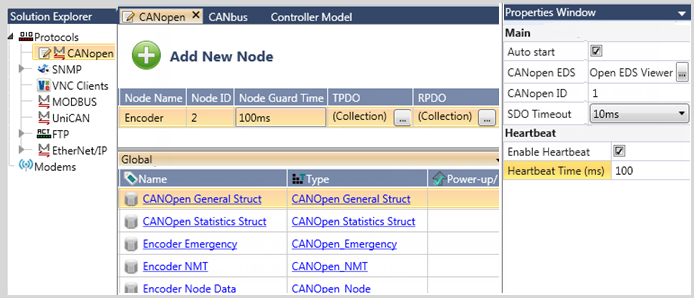
Select CANopen from the solution Explorer, and configure the CANopen properties as required.
You can also use an EDS file.
Note |
In the Properties window, note that the CANopen Master ID number must be unique, and not be assigned to a Node ID in your project. |
Property |
Purpose |
Auto start |
Unchecked by default. The Auto process sends an RTR to each node that is defined in the configuration, and waits for a reply. If any of the nodes do not answer, CANopen initialization fails. If all nodes are present, the controller broadcasts the command NMT1 - Start Remote Node. |
CANopen EDS |
You can open the EDS viewer and use it to open the EDS file of a node in your network |
CANopen ID |
This is the ID number of the controller. It must be unique, not used by any of the network nodes. The range is 1-127 |
SDO TimeOut |
The default is 10ms; click the drop-down arrow to select a new value. |
Select this to send a heartbeat from the PLC, according to the time interval specified in the parameter Heartbeat time. |
|
Heartbeat time (ms) |
The default is 100ms. The range is 100-100000ms (10 seconds) |
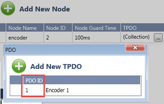
To add remote nodes:
Select CANopen in the Solution Explorer and click Add New Node.
In the Node table, Add TPDOs/RPDOs
by clicking the Collection fields.
Note that you can also import
an EDS file for the node.

Node Parameter |
Purpose |
Node Name |
Maximum of 40 characters |
Node ID |
This is the ID number of the node. It must be unique, not used by the controller or other nodes. The range is 1-127 |
Node Guard Time |
This sets the interval time for Node Guard checking. Default = 100ms Not in Use (0) means that the check will not be performed. |
TPDO |
Click on Collection to add data. This is the PDO data that is read/received from the node. You can define 4 TPDO Rx messages for each node. Maximum struct length is 32 bytes. If you use a bit array, note that these must be either be grouped in multiples of 8, OR set as an array of 8 bits where the number of bits is the array is a multiple of 8. |
RPDO |
Click on Collection to add data. This is the PDO data that is written/sent to the node when a Send PDO function runs. You can define 4 RPDO Tx messages for each node.
|
As you configure CANopen and add nodes, UniLogic automatically creates structs. Two structs support general CANopen Protocol function. As you add nodes, UniLogic creates three structs per node.
CANopen Protocol Structs
CANopen General StructCANopen General Struct
Parameter Name |
Type |
Purpose |
Initialization Status |
UINT32 |
The error index is decimal 0 - CANopen node: ok 1 - CANopen node: initialized 2 - CANopen node: initialising 3 - CANopen node: initialization error. Note that an Initialization Error may also generate a code in the SDO Abort parameter, described below. 4 - CANopen node: network auto start failed 5 - CANopen node: stop mode (happens when CPU is in Stop mode) 6 - CANopen node: operational 7 - CANopen node: internal error 8 - CANopen node: bad pointer 9 - CANopen node: bad input value 10 - CANopen node: bad packet 11 - CANopen node: bad node id 12 - CANopen node: bad PLC id 13 - CANopen node: bad index 14 - CANopen node: bad size 15 - CANopen node: bad buffer size 16 - CANopen node: bad sdo time out 17 - CANopen node: bad file pointer 18 - CANopen node: bad file size 19 - CANopen node: bad alignment tpdo struct 20 - CANopen node: bad alignment rpdo struct 21 - CANopen node: insufficient size 22 - CANopen node: insufficient buffer size 23 - CANopen node: alloc failed 24 - CANopen node: out of memory 25 - CANopen node: send failed 26 - CANopen node: rcv failed 27 - CANopen node: node error 28 - CANopen node: network error 29 - CANopen node: not initialized 30 - CANopen node: is initialized 31 - CANopen node: not enabled 32 - CANopen node: send queue full 33 - CANopen node: receive queue full 34 - CANopen node: PDO index invalid 35 - CANopen node: PDO not initialized 36 - CANopen node: node invalid id 37 - CANopen node: node initialization error 38 - CANopen node: node not initialized 39 - CANopen node: node missing 40 - CANopen node: node disabled 41 - CANopen node: SDO timeout 42 - CANopen node: SDO busy 43 - CANopen node: SDO node aborted 44 - CANopen node: SDO crc failed 45 - CANopen node: SDO toggle bit problem 46 - CANopen node: SDO max size 47 - CANopen node: SDO block error 48 - CANopen node: network reset
|
Master ID |
UINT16 |
This is the controller ID that is set in the CANopen properties. Read-only. |
Number of Nodes |
UINT16 |
The number of nodes that are in this application. |
SDO Timeout |
UINT32 |
This is the SDO Timeout value that is set in the CANopen properties. Read-only. |
SDO Abort Code |
UINT32 |
This value is from the remote Node, and indicate the status messages from the CANopen protocol. Read-only. |
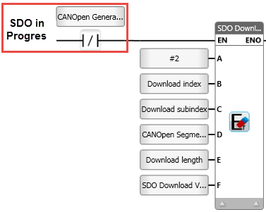
SDO in Progress |
BIT |
Is ON when SDO Read/Write is in Progress |
Disconnected Node ID |
UINT8 |
If Auto Start is selected, this tag contains the 1st disconnected node ID |
|
|
|
CANopen Statistics StructCANopen Statistics Struct
Parameter Name |
Type |
Definition |
CANopenGeneralError1 |
UINT32 |
Call Support |
CANopenGeneralError2 |
UINT32 |
Call Support |
CANopenGeneralError3 |
UINT32 |
Call Support |
SendQueueIsFull |
BIT |
|
ReceiveQueueIsFull |
BIT |
|
NumSendMsg |
UINT32 |
|
NumReceivedMsg |
UINT32 |
|
NumSendMsgDropped |
UINT32 |
|
NumReceivedMsgDropped |
UINT32 |
|
NumSendPDOMsg |
UINT32 |
|
NumSendPDORTRMsg |
UINT32 |
|
NumReceivedPDO1Msg |
UINT32 |
|
NumReceivedPDO2Msg |
UINT32 |
|
NumReceivedPDO3Msg |
UINT32 |
|
NumReceivedPDO4Msg |
UINT32 |
|
NumSendNodeGuardMsg |
UINT32 |
|
NumReceivedNodeGuardMsg |
UINT32 |
|
NumSendSYNCMsg |
UINT32 |
|
NumSendNMTControlMsg |
UINT32 |
|
NumSendTimeStampMsg |
UINT32 |
|
NumSendSDOWrite |
UINT32 |
|
NumReceivedSDOWrite |
UINT32 |
|
NumSendSDORead |
UINT32 |
|
NumReceivedSDORead |
UINT32 |
|
NumReceivedEmergency |
UINT32 |
|
Node Structs
CANopen Emergency StructCANopen Emergency Struct
The parameters in this struct support the Emergency Object as defined in the CANopen protocol.
Parameter Name |
Type |
Purpose |
Error Code |
UINT16 |
Emergency Error Code The 'xx' part of the codes in this list is defined by the appropriate device profile. 00xx - Error Reset or No Error 10xx - Generic Error 20xx - Current 21xx - Current, device input side 22xx - Current, inside the device 23xx - Current, device output side 30xx - Voltage 31xx - Mains voltage 32xx - Voltage inside the device 33xx - Output voltage 40xx - Temperature 41xx - Ambient temperature 42xx - Device temperature 50xx - Device hardware 60xx - Device software 61xx - Internal software 62xx - User software 63xx - Data set 70xx - Additional modules 80xx - Monitoring 81xx - Communication 8110 - CAN overrun 8120 - Error Passive 8130 - Life Guard Error or Heartbeat Error 8140 - Recovered from Bus-Off 82xx - Protocol Error 8210 - PDO not processed due to length error 8220 - Length exceeded 90xx - External error F0xx - Additional functions FFxx - Device specific |
Error Register |
UINT8 |
Bit definition of the 8-bit Error Register (Object 0x1001 in the CANopen Object Dictionary). 0 generic 1 current 2 voltage 3 temperature 4 communication 5 device profile specific 6 reserved (=0) 7 manufacturer specific |
Manufacturer Specific |
UINT8
Array |
Manufacturer Specific Error Field |
Received Bit |
BIT |
Turns ON when an Emergency message is received. Reset by User |
Node Data StructNode Data Struct
Parameter Name |
Type |
Purpose |
Node ID |
UINT16 |
The
available range is Read-only. |
Enable Node Bit |
BIT |
0= The node is excluded from Autostart and disabled 1= Included in Autostart and enabled |
Receive Bit TPDO |
Array, 4 bits |
When a PDO is transmitted from a node, a bit turns ON when it is received by the controller. Reset by user. 0=TPDO 1 1=TPDO 2 2=TPDO 3 3=TPDO 4 |
Number of TPDO |
UINT16 |
Number of TPDO messages configured by user. Read-only. |
Number of RPDO |
UINT16 |
Number of RPDO messages configured by user. Read-only. |
Node Guard Time |
UNIT32 |
From Node Data. Read-only. |
Initialization Status |
UINT8 |
The error index is decimal 0 - CANopen node: ok 1 - CANopen node: initialized 2 - CANopen node: initialising 3 - CANopen node: initialization error. Note that an Initialization Error may also generate a code in the SDO Abort parameter, described below. 4 - CANopen node: network auto start failed 5 - CANopen node: stop mode (happens when CPU is in Stop mode) 6 - CANopen node: operational 7 - CANopen node: internal error 8 - CANopen node: bad pointer 9 - CANopen node: bad input value 10 - CANopen node: bad packet 11 - CANopen node: bad node id 12 - CANopen node: bad PLC id 13 - CANopen node: bad index 14 - CANopen node: bad size 15 - CANopen node: bad buffer size 16 - CANopen node: bad sdo time out 17 - CANopen node: bad file pointer 18 - CANopen node: bad file size 19 - CANopen node: bad alignment tpdo struct 20 - CANopen node: bad alignment rpdo struct 21 - CANopen node: insufficient size 22 - CANopen node: insufficient buffer size 23 - CANopen node: alloc failed 24 - CANopen node: out of memory 25 - CANopen node: send failed 26 - CANopen node: rcv failed 27 - CANopen node: node error 28 - CANopen node: network error 29 - CANopen node: not initialized 30 - CANopen node: is initialized 31 - CANopen node: not enabled 32 - CANopen node: send queue full 33 - CANopen node: receive queue full 34 - CANopen node: PDO index invalid 35 - CANopen node: PDO not initialized 36 - CANopen node: node invalid id 37 - CANopen node: node initialization error 38 - CANopen node: node not initialized 39 - CANopen node: node missing 40 - CANopen node: node disabled 41 - CANopen node: SDO timeout 42 - CANopen node: SDO busy 43 - CANopen node: SDO node aborted 44 - CANopen node: SDO crc failed 45 - CANopen node: SDO toggle bit problem 46 - CANopen node: SDO max size 47 - CANopen node: SDO block error 48 - CANopen node: network reset |
EDS Init in Progress |
Bit |
Turns ON when initialization begins, turns OFF when initialization is finished. Read-only. |
EDS Init Success |
Bit |
Resets automatically when initialization begins. Turns ON if the EDS file was successfully
initialized to the node. |
EDS Init Failed |
Bit |
Resets automatically when initialization begins. Turns ON if the EDS file fails to be initialized
to the node. |
EDS Init Error Code |
UINT32 |
0 – Initialization OK 5 – EDS initialization failed because the controller entered Stop mode 41 – SDO has timed out 43 – SDO was aborted, refer to the SDO abort code For any other codes –note the code, and contact support |
EDS Init Error String |
String |
If the EDS Init Error Code is not 0, indicating that an error has occurred, this string reports the first SDO that was not successfully downloaded to the device. |
Reset Node in Progress |
Bit |
Turns ON when node reset begins, turns OFF when node reset is finished. Bit is reset automatically when reset begins. |
Reset Node Success |
Bit |
Bit is Reset automatically when initialization begins. Turns ON if the node was successfully reset. |
Reset Node Failed |
Bit |
Bit is Reset automatically when initialization begins. Turns ON if the node was not successfully
reset. |
Reset Node Error Code |
UINT32 |
0 – Node Reset Success 41 – SDO has timed out 43 – SDO was aborted. This may be because the device EDS file does not enable reset. Refer to the SDO abort codes that are defined in the CANopen protocol. 51 – A Node Reset request is already in progress For any other codes –note the code, and contact support |
Node NMT StructNode NMT Struct
Parameter Name |
Type |
Purpose |
Status |
UINT8 |
0 Initializing 4 Stopped 5 Operational 127 Pre-operational |
Toggle Bit |
BIT |
Each time the remote node sends an NMT to the controller, the status of this bit is toggled at each send. |
Toggle Bit Problem |
BIT |
This bit turns ON if the controller receives 2 consecutive messages with the SAME Toggle bit status. Reset by user. |
Note |
When the controller begins CANopen initialization, it starts by sending NMT 130 = Reset communication |
UniStream supports the following Ladder functions:
Use this function to download (write) a segment block of data (bytes) from the controller's Input Buffer to a node.
Download SDO using the required parameters: Index, Sub-Index, value to send, length according to the EDS file of your device.
|
Notes |
|
|
|
Parameter |
Type |
Purpose |
|
A |
Node ID |
UINT |
Enter a constant or tag value to supply the ID of the remote device |
|
B |
Index |
UINT16 |
The index of the remote device. |
|
C |
Sub-Index |
UINT16 |
The Sub-Index of the remote device. |
|
D |
Segment Transfer Type |
Selection |
Select either:
|
|
E |
Number of Bytes to Download |
UINT |
Data length to write to remote device (bytes) Max=40 bytes |
|
F |
Input Buffer |
Register |
Assign a register, buffer, or string to contain the data that is transmitted to the remote device. |
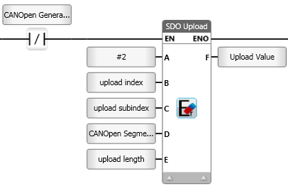
Use this function to upload (read) a segment block of data (bytes) from a node to the Output Buffer in the controller.
Upload SDO using the required parameters: Index, Sub-Index, value to send, length according to the EDS file of your device.
|
Notes |
|
|
|
Parameter |
Type |
Purpose |
|
A |
Node ID |
UINT |
Enter a constant or tag value to supply the ID of the remote device |
|
B |
Index |
UINT16 |
The index of the remote device. |
|
C |
Sub-Index |
UINT16 |
The Sub-Index of the remote device. |
|
D |
Segment Transfer Type |
Selection |
Select either:
|
|
E |
Number of Bytes to Download |
UINT |
Data length to read from the remote device (bytes) Maximum=40 bytes |
|
F |
Output Buffer |
Register |
Assign a register, buffer, or string to contain the data that is transmitted to the remote device. |
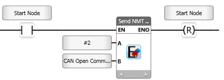
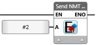
Send NMT ControlSend NMT Control
This function enables you to send NMT Control messages.
Send NMT control
|
|
Parameter |
Type |
Purpose |
|
A |
Node ID |
UINT |
Enter a constant or tag value to supply the ID of the remote device. ID 0 in order to broadcast from to all nodes. |
|
B |
Command |
UINT16 |
Select Command: 1 Start Remote Node 2 Stop Remote Node 128 Enter Preoperational State 129 Reset Node 130 Reset Communication
|
Send NMT Node GuardSend NMT Node Guard
This is sometimes referred to as a 'heartbeat check'.
The Send NMT Node Guard function provides CANopen
Node Guarding, checking node status.
The status returned from the node is stored in the node's NMT struct.
|
|
Parameter |
Type |
Purpose |
|
A |
Node ID |
UINT |
Enter a constant or tag value to supply the ID of the remote device |
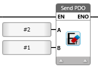
Send PDO/Send PDO RTRSend PDO/Send PDO RTR
The Send PDO function writes data to the node from the PLC master.
The Send PDO RTR function request data from the node, and reads data from the node to the PLC master.
|
|
Parameter |
Type |
Purpose |
|
A |
Node ID |
UINT |
Enter a constant or tag value to supply the ID of the remote device |
|
B |
PDO ID |
UINT16 |
Select the number of the PDO assigned in the CANopen Configuration. CANopen Configuration.
|
Use this function to synchronize tasks across the network.

Use this function to send a time stamp.

If you are using an EDS file, use the following Ladder Functions to write values to the EDS parameters via SDO.
Use these functions to initialize the device with the values that you have edited or entered via UniLogic's EDS utility. In your program, use the In Progress bits to condition the functions.
Init Node EDS
Use this function to initialize a specific node with the values edited or entered via UniLogic's EDS utility.
Init All Nodes EDS
Use this to initialize all of the CANopen nodes in your project with the values edited or entered via UniLogic's EDS utility.
Restore Node Defaults
If your CANopen device enables this function, which refers to object 1011 in the node's dictionary, you can use this to reset all of the node's addresses to the manufacturer's default values.
Note |
If Restore Node Defaults is included in the program, but is not supported by the device, UniLogic issues a compilation warning. |
The status of these functions and error messages are provided in the Node Data Struct.

 If you use a
bit array, note that these must be either be grouped in multiples
of 8, OR set as an array of 8 bits where the number of bits is
the array is a multiple of 8.
If you use a
bit array, note that these must be either be grouped in multiples
of 8, OR set as an array of 8 bits where the number of bits is
the array is a multiple of 8.