UniCAN is Unitronics' proprietary CANbus protocol. UniCAN is controlled by configuration. The controller automatically sends messages according to the time intervals that you set in the UniCAN configuration. UniCAN uses 29-bit extended identifiers. |
|
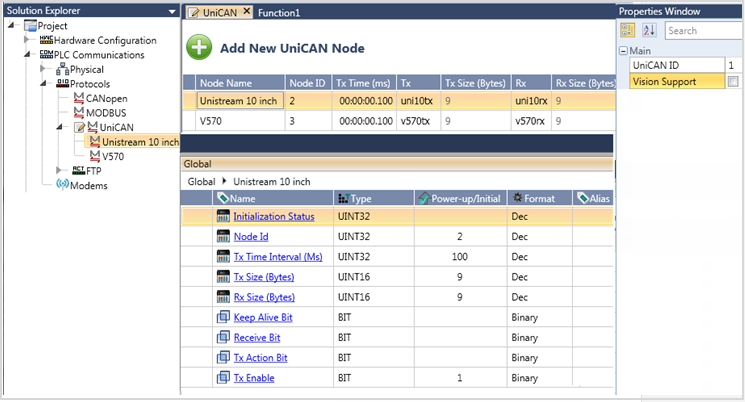
On the Solution Explorer tree, click PLC Communications to expand it, then Protocols, and then UniCAN; this opens the configuration.
The Properties window shows the Unit ID of the controller. Note that this number must NOT match the number of any of the UniCAN nodes.
Click Add New UniCAN Node. Note that UniLogic automatically assigns a Node ID number to each node.
Node Parameters
Name |
Definition |
Node Name |
The name of the remote network node. |
Node ID |
The ID number of the remote node on the network |
Tx Time (ms) |
Enter the time intervals for the controller to send messages to this node.. |
Tx |
Select the tag or struct that the controller will send. |
Tx Size |
Read-only. This shows the byte length of the data to be sent. |
Rx |
Select the tag or struct that the controller use to store the data received from this node. |
Rx Size |
Read-only. This shows the byte length of the tag or struct that is to store the received data. |
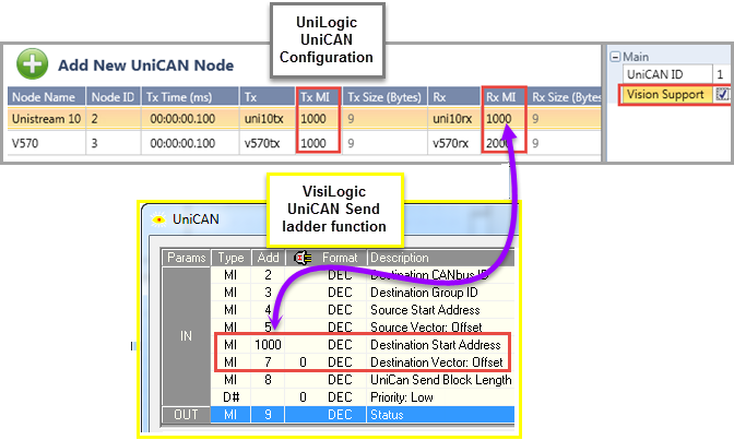
In order to communicate with Vision controllers, check the property Vision Support. This enables UniStream:
To send messages to Vision controllers. Checking Vision Support adds a Tx parameter: Tx MI. Tx MI sets the start address of the destination vector in the Vision controller. UniStream sends the contents of the Tx data tag to Vision. Vision writes the Tx data into this destination vector, which starts with the address set in Tx MI.
To receive messages from Vision controllers. Checking Vision Support adds an Rx parameter: Rx MI. The VisiLogic program in the Vision controller sends data via Send UniCAN ladder function. In this function, note that the parameter Destination Start Address must match the UniLogic parameter Rx MI, and the Destination Vector: Offset must be set to 0.
.
Note |
|
UniCAN Structs
When you configure UniCAN, UniLogic creates two structs that enable you to manage and monitor UniCAN, plus an individual struct for each node.
UniCAN General Struct
Name |
Data Type |
Definition |
Initialization Status |
UINT32 |
0= OK If there is any other value, check the parameter Initialization Status in each UniCAN Node struct in order to see the error. |
UniCAN ID |
UINT32 |
Read-only. This is the number from the UniCAN configuration |
Number of Nodes |
UINT32 |
Read-only. This is the number of Nodes defined in the configuration |
Alive Error Exists |
Bit |
Each 0.5 seconds, a unit sends an 'Alive' signal to the CANbus network. If any unit is faulty, and does not send an Alive signal, this bit turns ON. |
UniCAN Statistics Struct
Name |
Data Type |
Definition |
UniCAN ID |
UINT32 |
This is the ID of this controller |
Rx Counter |
UINT32 |
The total number of Rx messages received by this controller |
Tx Counter |
UINT32 |
The total number of Tx messages sent by this controller |
Rx Alive Counter |
UINT32 |
The total number of Alive signals received by this controller |
Tx Alive Counter |
UINT32 |
The total number of Alive signals sent by this controller |
Rx Error Counter |
UINT32 |
This is the total number of errors received from all nodes by this controller, including: Message size mismatch, Message received from undefined node ID, MI received that is not defined in the Rx MI parameter |
Tx Error Counter |
UINT32 |
Total number of messages that could not be sent |
Rx Alive Error Counter |
UINT32 |
The total number of Alive errors received by this controller |
Tx Alive Error Counter |
UINT32 |
The total number of Alive errors sent by this controller |
Alive Bitmap 1-31 |
UINT32 |
When a Keep Alive signal is not received from a specific node, the corresponding bit indicating the node ID turns ON. (Nodes 1-31) |
Alive Bitmap 32-63 |
UINT32 |
When a Keep Alive signal is not received from a specific node, the corresponding bit indicating the node ID turns ON. (Nodes 32-63) |
UniCAN Node Struct
Name |
Data Type |
Definition |
Initialization Status |
UINT32 |
Contact support = 0x02, TX_ALIGNMENT_MSG_ERROR = 0x03, RX_ALIGNMENT_MSG_ERROR = 0x04, TX_MI_ERROR = 0x03, RX_MI_ERROR = 0x04, |
Node ID |
UINT32 |
The ID of this specific node |
Tx Time Interval (Ms) |
UINT32 |
Read/write. Tis is the interval at which this node sends message (Note that Tx enable must be ON) |
Tx Size (bytes) |
UINT32 |
Read-only |
Rx Size (bytes) |
UINT32 |
Read-only |
Rx Error Counter |
UINT32 |
This is the total number of errors for this node, including: Message size mismatch, Message received from undefined node ID, MI received that is not defined in the Rx MI parameter |
Keep Alive Bit |
Bit |
1= OK . This means that a Keep Alive signal was received for this node. 0= No Keep Alive received for this node |
Receive Bit |
Bit |
A message is in the Rx parameter tag. Initialized by user. Note that this will not turn ON until all of the bytes in the Rx message have been received. |
Tx Action Bit |
Bit |
Turn this ON to force a message to be sent without regard to the defined interval. (Note that Tx enable must be ON) |
Tx Enable |
Bit |
0= Disable Send 1= Enable Send |