The CAN Layer 2 Ladder functions enable communication via any CANbus protocol.
UniStream controllers support data communication with remote devices such as frequency converters according to the CANbus V2.0 standard.
A controller can both send and receive standard messages with 11-bit identifiers, as well as extended messages with 29-bit identifiers. In UniLogic, you use a Buffer data type to provide data to the CANbus data frame, as well as to receive data. Note that although a UniLogic buffer may be of any length, the CANbus protocol limits the data frame to 8 bytes for all messages.
Use this to send messages and determine the data that is sent to a specified remote device.
|
Note |
Prevent CANbus network overload by using a condition to activate Send functions. Do not place them directly on the left Ladder rail. |
|
|
Parameter Name |
Type |
Purpose |
|
A |
Message Identifier |
UINT32 |
This is the ID of the message that is sent. |
|
B |
Identifier Type |
Bit |
Set the CAN Identifier type:
|
|
C |
Buffer |
Buffer |
This buffer will be sent in the message's data frame. Note that CANbus limits the data frame to 8 bytes |
|
F |
Number of Bytes to Send |
INT/UINT 8-32 |
Limits the number of bytes that will be sent in the data frame. |
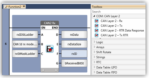
Use this function to receive messages. In order to continually monitor the network, place Receive functions on the left Ladder rail.
|
|
You must limit your application to two Rx functions. Each must use a different Identifier Type.
|
|
|
Identifiers
|
|
Note |
|
|
|
Parameter Name |
Type |
Purpose |
|
A |
Identifier: Message(s) to Receive |
UINT32 |
This determines which messages may be received by the function. 11-bit ID, range: 0-2047 29-bit ID, range 0-536870911 |
|
B |
ID Identifier Type |
Bit |
Set the CAN Identifier type:
|
|
C |
Mask |
UINT32 |
Provides a method to filter which messages are received. |
|
D |
Buffer |
Buffer |
This is where the data of the received message is stored. |
|
E |
Number of Receive Bytes |
INT/UINT 8-32 |
This is the number of bytes that have been received from the message. |
|
F |
Received Identifier |
INT/UINT 16/32 |
Stores the Identifier of the incoming message. |
|
G |
Received Bit |
Bit |
Turns ON when message received. Reset by user. |
Filtering Messages: Identifiers and Mask
You can filter incoming messages by using the Mask parameter. The controller compares the Identifier value in parameter A, to the Identifier of incoming messages and runs an algorithm to determine whether to receive the message according to the value in parameter C, Mask.
Use Mask values as follows:
To limit the function and receive only messages with an identifier that matches the one in Parameter A, set the Mask parameter to 0x7FF for 11-bit identifiers, or 0x1FFFFFFF for 29-bit.
To enable the function to receive all messages from all devices set the Mask parameter to 0.
To limit the function to receiving messages from a range of devices, you can use the Mask as shown in the following example.
The filtering algorithm compares the binary values of Parameter A, Identifier, to the Identifier of incoming messages. It compares the status of each bit according to the mask value as follows: if a mask bit is set to 1, the algorithm compares the corresponding bits of the message Identifiers. If a mask bit is set to 0, the algorithm ignores the corresponding bit of the identifiers.
In the following example, the programmer wishes to receive messages from Units 3,6,7. In order to do this, the Identifier to binary 0000 0000 1x1x, Mask may be set to binary 1111 1111 1x1x. Note that x=ignore--meaning that these bit values will not be compared.
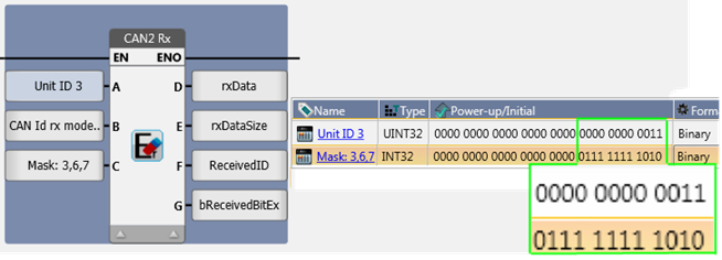
Note that the mask value 0x7FA, shown in binary below, enables messages to be received from Units 3,6,7, but that they will also cause the messages from Unit 2 to be received .
| Unit ID | LSB | ||||
| 0 | 0000 | 0000 | 0000 | Accept ALL messages | |
| Device # | 1 | 0000 | 0000 | 0001 | |
| 2 | 0000 | 0000 | 0010 | Will also be received | |
| 3 | 0000 | 0000 | 0011 | Received | |
| 4 | 0000 | 0000 | 0100 | ||
| 5 | 0000 | 0000 | 0101 | ||
| 6 | 0000 | 0000 | 0110 | Received | |
| 7 | 0000 | 0000 | 0111 | Received | |
| 8 | 0000 | 0000 | 1000 | ||
| 9 | 0000 | 0000 | 1001 | ||
| 10 | 0000 | 0000 | 1010 | ||
| 11 | 0000 | 0000 | 1011 | ||
| 12 | 0000 | 0000 | 1100 | ||
| 13 | 0000 | 0000 | 1101 | ||
| 14 | 0000 | 0000 | 1110 | ||
| 15 | 0000 | 0000 | 1111 | ||
| ID | 0000 | 0000 | 0x1x | ||
| MASK | 0111 | 1111 | 1010 |
Use this function to request data from the remote device specified in parameter A, Unit ID.
|
|
Parameter Name |
Type |
Purpose |
|
A |
Unit Identifier, Remote Device |
UINT32 |
This is the Identifier of the device you are requesting data from. |
|
B |
ID Identifier Type |
Bit |
Set the CAN Identifier type:
|
This function answers RTR data requests, if the message Identifier matches the ID must match the ID of the requesting device
|
|
Parameter Name |
Type |
Purpose |
|
A |
Identifier |
UINT32 |
When the ID of the incoming message matches the Identifier, the controller sends the buffer data. |
|
B |
ID Identifier Type |
Bit |
Set the CAN Identifier type:
|
|
D |
Buffer |
Buffer |
This buffer will be sent in the message's data frame. Note that CANbus limits the data frame to 8 bytes |
|
E |
Number of Bytes to Send |
INT/UINT 8-32 |
Limits the number of bytes that will be sent from the buffer. |
|
F |
Response Index Number |
1-4 |
Use this to assign a number to the response. |
ErrNo Codes
Functions
SysFuncId_CANLayer2Tx = 0x00E3,
SysFuncId_CANLayer2TxRTR = 0x00E4,
SysFuncId_CANLayer2Rx = 0x00E5,
SysFuncId_CANLayer2RTRResponse= 0x00E6,
Error codes
CANLayer2_OK = 0x00,
CANLayer2_GeneralErr = 0x01,
CANLayer2_LengthErr = 0x02,
CANLayer2_CANBusErr = 0x03,
CANLayer2_IdTypeErr = 0x04,
CANLayer2_TxStIdErr = 0x05,
CANLayer2_TxExIdErr = 0x06,
CANLayer2_TxStFullQueue = 0x07,
CANLayer2_TxExFullQueue = 0x08,
CANLayer2_RxStInitErr= 0x09,
CANLayer2_RxExInitErr= 0x0A,
CANLayer2_RTRRwsponseIndexErr= 0x0B,
CANLayer2_RTRRwsponsInitErr = 0x0C,
