Remote I/Os: via EX-RC1, EXF-RC15
You can include Remote I/Os in your application via the EX-RC1 adapter or the EXF-RC15 , using files that are ported between VisiLogic and UniLogic.
The EX-RC1 adapter enables you to distribute I/O Expansion Modules throughout your system. The adapter communicates with UniStream devices over CANbus via UniCAN, Unitronics’ proprietary CANbus protocol, and functions as a slave device within that network. Up to 8 EX-RC1 adapters can be included in a project. Each adapter may be connected to up to 8 I/O expansion modules.
The EXF-RC15 is a stand-alone module with high-speed I/Os. It offers 9 digital inputs, 4 digital transistor outputs, and 2 relay outputs. Three inputs can be set via wiring and software to function as high-speed counters/shaft-encoders. The four transistor outputs may function as high-speed PWM/PTO outputs.
Data
You can communicate two kinds of data between UniStream and the EX-RC1 adapter.
-
I/O Data: to/from the modules that are connected to the adapter.
-
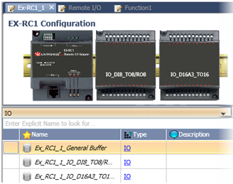
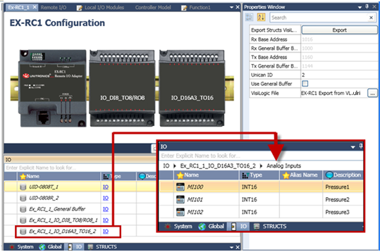
General Buffer Data: Select this option to send/receive a 16-register long vector of data. These vectors are part of the data struct that UniLogic creates for each adapter that is included in the project.
The structs containing the data are shown in the image to the right.
|
|
|
Note
|
Set the identical baud rate in both projects:
-
Adapter Initialize the CANbus port via Com> Com Init, set to UniCAN. Selecting UniCAN enables you to set the baud rate.
-
UniLogic Access Solution Explorer > PLC Communications> Physical > CANbus. This opens the Baud Rate in the Properties Window.
|
|
|
Make sure that the CANbus PLC ID numbers match:
-
Adapter The ID number is set by DIP switch, according to the method explained in the Remote I/Os topic of the VisiLogic help file.
-
UniLogic Access Solution Explorer > Hardware Configuration>Remote I/O and set the ID in the Properties Window.
|
Step 1: Export EX-RC1, EXF-RC15 Operand Files from VisiLogic
The examples below use the EX-RC1. Note that the EXF-RC15 is a stand-alone module with high-speed I/Os. The principles of Export are the same.
-
Download the VisiLogic Beta version from http://www.unitronics.com/Content.aspx?page=Downloads.This version comprises an add-in that enables you to export EX-RC1 files.
-
Create your EX-RC1 application in Visilogic, including Hardware Configuration.
-
In Hardware Configuration, right-click on EX-RC1, and then click Export.
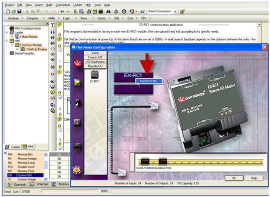
-
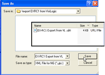
Save the resulting .ulri file.
Step 2: The UniLogic project
-
Select Remote I/O from the Solution Explorer, and then click Add New RIO-RC.
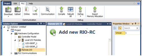
-
In the Properties Windows, click to import the VisiLogic.ulri file.Properties Windows, click to import the VisiLogic.ulri file.
|
|
|
Export Structs to VisiLogic
|
Exports an .ulri XML file that you import to Visilogic via the Vector> Structs function. This file automatically writes the operand addresses into the VisiLogic Struct function.
|
|
Rx Start Vector
|
Start address for storing the MI vector of Input data, which the EX-RC1 sends to the UniStream controller. This is a set address that cannot be changed.
In your VisiLogic application, use this address in UniCAN Send for both the Source Start Address and Destination Start Address.
|
|
Rx General Buffer
|
Start address of a vector that is 16 registers long. This is a set address that cannot be changed.
If Use General Buffer is selected, and the EX-RC1 sends General Data via a Send Message function, use this address in UniCAN Send for both the Source Start Address and Destination Start Address.
|
|
Tx Start Vector
|
Start address for the MI vector of Output data, which UniStream sends to the EX-RC1. This is a set address that cannot be changed.
The EX-RC1 stores it in the vector starting from this address.
|
|
Tx General Buffer
|
Start address of a vector that is 16 registers long. This is a set address that cannot be changed.
If Use General Buffer is selected, UniStream sends the buffer data to the EX-RC1. The EX-RC1 stores the data in the vector beginning form this address.
|
|
Use General Buffer
|
Select this to enable Rx and Tx General Buffer data.
|
| |
|
|
|
|
Export Structs to VisiLogic
|
Exports an .ulri XML file that you import to Visilogic via the Vector> Structs function. This file automatically writes the operand addresses into the VisiLogic Struct function.
|
|
Rx Start Vector
|
Start address for storing the MI vector of Input data, which the EX-RC1 sends to the UniStream controller. This is a set address that cannot be changed.
In your VisiLogic application, use this address in UniCAN Send for both the Source Start Address and Destination Start Address
|
|
Rx General Buffer
|
Start address of a vector that is 16 registers long. This is a set address that cannot be changed.
If Use General Buffer is selected, and the EX-RC1 sends General Data via a Send Message function, use this address in UniCAN Send for both the Source Start Address and Destination Start Address
|
|
Tx Start Vector
|
Start address for the MI vector of Output data, which UniStream sends to the EX-RC1. This is a set address that cannot be changed.
The EX-RC1 stores it in the vector starting from this address.
|
|
Tx General Buffer
|
Start address of a vector that is 16 registers long. This is a set address that cannot be changed.
If Use General Buffer is selected, UniStream sends the buffer data to the EX-RC1. The EX-RC1 stores the data in the vector beginning form this address.
|
|
Use General Buffer
|
Select this to enable Rx and Tx General Buffer data.
|

-
VisiLogic imports the EX-RC1 configuration, including the operand descriptions, to the UniLogic project.
Step 3: Mapping Data Structs in VisiLogic
-
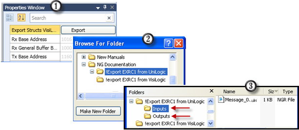
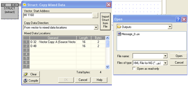
Export the data struct by clicking Properties Window> Export Structs VisiLogic, and saving the .ulri file.
Note that the Export creates two folders, one for Inputs and one for Outputs.ulri
-
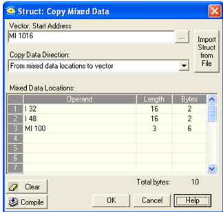
In the VisiLogic project, in the Ladder application, place a Vector> Struct function, and then click Import Struct from File. Navigate to the Inputs file.
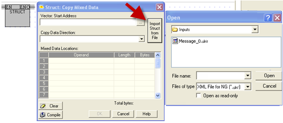
-
After you import the file, you can see the data addresses. Note that you must compile the function in order to activate the OK button.
-
Repeat the import process for the Output data struct.
-
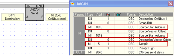
In your VisiLogic application, check that in the UniCAN Send function used to send the data to UniStream:
-
The Source Start Address matches the Start Address in the Struct function.
-
The Destination Start Address matches the Start Address in the Struct function.
Since both of these parameters must be addressed to the same MI, they will have the same description; however Parameter #5 is indeed Destination Start Address. This is shown in the following image, where both Source Start and Destination Start are addressed to MI1016.
-
Length is the number of MIs in the vector; make sure that the vector length is long enough to take all of the required data from the EXRC1 to the UniStream.
General Buffer
When you select Use General Buffer, UniStream will send the General Buffer contents to the EX-RC1 adapter.
-
If you are sending General Buffer data, make sure that you have selected Use General Buffer in the Properties Window.
-
Include a UniCAN send function that uses the General Buffer Tx address.
If you are connected to the Internet, you can access this UniLogic tutorial:
UniStream: Remote I/O via EX-RC
Related Topics
Hardware Configuration
Configuring Digital I/Os
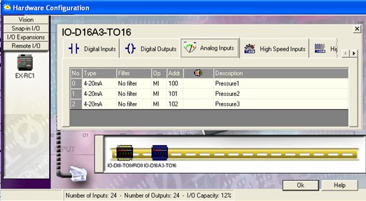
Configuring Analog I/Os