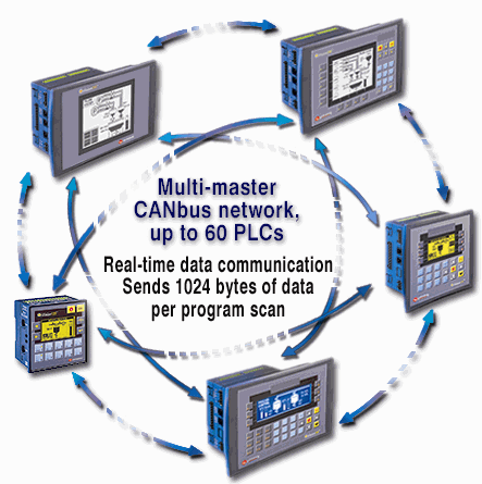
UniCAN enables fast data communications. Via UniCAN, a Unitronics' PLC can exchange data with up to 60 other networked PLCs. A UniCAN application can send up to 32 messages, each containing 16 integer values, totaling 512 MI register values during a single program scan.

When PLCs are connected to the CANbus network and their CANbus ports initialized to UniCAN, you can use the UniCAN functions, located on the Communications menu, to transfer data between units or check a unit's status.
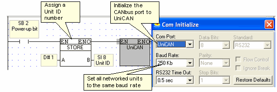
Before using UniCAN functions, assign each networked controller a unique Unit ID number and initialize the CANbus port to UniCAN. Note that you can run both UniCAN and CANopen if you select the relevant Com Port option in the COM Init function.
|
Note ♦ |
Baud Rate is a function of cable length, as described in CANbus Hardware Specifications. |
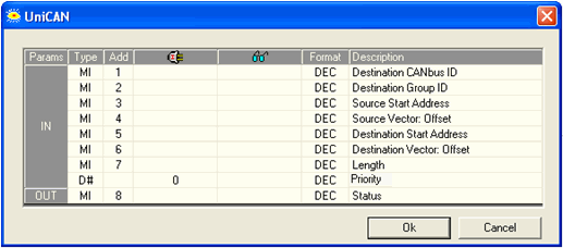
The Send function enables you to:
Read a vector of MIs in the source PLC
Write the values to a vector in a target PLC on the CANbus network
You can send a vector of values up to 16 integers long in a single Send function.
|
Parameter |
Type |
Function |
||||||||||||||||||||||
|
Destination CANbus ID |
Constant or MI |
The CANbus ID number of the target PLC. |
||||||||||||||||||||||
|
Destination Group ID |
Not currently supported. Enter ID0. |
|||||||||||||||||||||||
|
Source Start Address |
MI |
The start address of the source vector in the source PLC. |
||||||||||||||||||||||
|
Source Vector: Offset |
Constant or MI |
The offset from the start address in the source PLC. |
||||||||||||||||||||||
|
Destination Start Address |
MI |
The start address of the destination vector in the target PLC. |
||||||||||||||||||||||
|
Destination Vector: Offset |
Constant or MI |
The offset from the destination address in the target PLC. |
||||||||||||||||||||||
Vision controllers can send and receive up to 32 bytes per message. UniStream controllers can send and receive up to 64 bytes. Note that you can use the parameter Offset in Buffer to manage receiving longer messages from UniStream. More details are in the UniLogic Help file. |
||||||||||||||||||||||||
|
Length |
Constant or MI |
This determines the length of the MI vector that is read from the source PLC and then written to the target PLC. |
||||||||||||||||||||||
|
Priority |
Constant |
Select High or Low priority. UniCAN uses 2 Send Message buffers, one for High Priority and one for Low Priority. High Priority messages are always sent first. Each buffer is based on a FIFO stack that may contain up to 16 messages containing up to 16 MIs each, a total of 512 integer values for both buffers. |
||||||||||||||||||||||
|
Status |
MI |
The Status MI indicates status and error messages as listed below. The Status MI updates when the Send function is activated. If an error occurs, the status indication updates. If there is no error, and the message is sent to the buffer, the status is 1. Once the message is sent, the MI updates to 0.
Note that each Send operation has its own Status MI.
The Status MI should be initialized at Power-up.
|
||||||||||||||||||||||
|
Note ♦ |
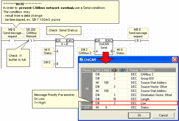
In order to prevent CANbus network overload, use a Send condition. Do not place the Send function directly on the left Ladder rail. |
|
|
When a buffer is full, the related SB turns ON. Check the buffer status by using an inverted contact of the relevant SB as a Send condition: SB 201: High Priority Buffer, SB 202 Low Priority Buffer. |
|
♦ |
Check the Status MI before Send. |
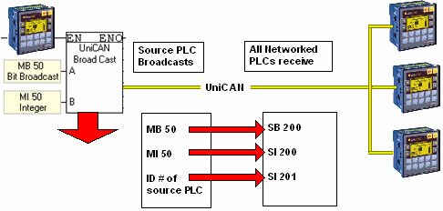
Use Broadcast to send an MB and an MI value to all controllers in the UniCAN network.
Each networked controller receives the values into system operands: the MB into SB 200, the MI into SI 200, and ID # of the source controller into SI 201.
|
Note ♦ |
SB 200, SI 200 and SI 201 must be initialized by the user. |
|
♦ |
A new Broadcast overwrites any previous values. The values remain until they are overwritten or initialized. |
|
♦ |
Use an inverted contact of SB 203, UniCAN Broadcast in Progress, as a Broadcast condition. |
If the source controller in the figure below is assigned ID# 3, contains 123 in MI 50, and has MB 50 ON: all controllers in the network will have 3 written into SI 201, 123 written into SI 200, and SB 200 will be turned ON.
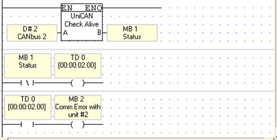
Each 0.5 seconds, a unit sends an 'Alive' signal to the CANbus network. The Check Alive Signal function receives the signal.
When the signal for the networked unit whose ID # is given is received, the Status MB turns ON for a single scan. This short time period means that you will not be able to see the signal in Online mode.
In the nets below, if an 'Alive' signal from PLC #2 is not registered for 2 seconds, the program turns on an error bit.
Message Arrived should be placed on the left-hand Ladder rail.
When a message arrives from the networked unit whose ID # is given in the function, the Status MB turns ON.
When the message is received, the corresponding bit in SIs-240-243, which provide a bitmap of all units in the UniCAN network, turns OFF.

|
SB# |
Description |
Turned ON |
Turned Off |
Comments |
|
200 |
Broadcast bit |
When UniCAN broadcast MB is received whose status is ON. |
When UniCAN broadcast MB is received whose status is OFF. |
The user must initialize this SB |
|
201 |
High Priority Send Buffer Status |
When full |
When not full |
Use the negative transition of this SB as a Send UniCAN condition for High Priority messages |
|
202 |
Low Priority Send Buffer Status |
When full |
When not full |
Use the negative transition of this SB as a Send UniCAN condition for Low Priority messages |
|
SI# |
Description |
Comments |
|
200 |
When a UniCAN Broadcast message is received, SI 200 contains the ID number of the sending unit. |
The user must initialize these SIs |
|
201 |
When a UniCAN Broadcast message is received, SI 201 contains the value of the MI that is broadcast. |
|
|
202 |
Number of Send messages waiting in High Priority buffer |
Automatically updates |
|
203 |
Number of Send messages waiting in Low Priority buffer |
|
|
204 |
Number of Received messages waiting in buffer |
|
|
240 |
These provide a bitmap of controllers 1-60 in the UniCAN network. |
When the controller receives a message, the appropriate bit turns ON. These bits are reset by the Answer Received function. |
|
241 |
||
|
242 |
||
|
243 |
|
SDW# |
Description |
Comments |
|
24 |
If not 0, contact technical support |
|
|
26 |
Send message counter. Note that only messages sent from a UniCAN Send are counted |
SDW 26 and 28 are initialized at COM Init. |
|
28 |
Receive message counter. Note that only messages received from a UniCAN Send are counted, not Broadcast messages or Check if Alive responses. |