The UniStream PLC is a line of PLC + Built-in I/O controllers that are mounted on a DIN-rail. Unlike other UniStream Controllers, this controller does not include a built-in HMI screen.
All UniStream PLCs can display HMI screens via 'Virtual HMI'. This means that you design your HMI application in UniLogic in exactly the same way as for any other UniStream controller. You can display the HMI on:
-
UniStream Displays (USL), included in this release. UniStream Displays are a series of color touch-screens that support VNC
-
UniStream Modular HMI panels (USP)
-
UniStream Built-in (on the panels integral to the device)
-
Any device screen that supports VNC
About UniStream PLC
The series is available in three versions: Pro, Standard, and Basic.
Note that a model number that includes:
-
B10 refers to Pro version (e.g. USC-B10-T24)
-
B5 refers to Standard version (e.g. USC-B5-RA28)
-
B3 refers to Basic version (e.g. only for USC-B3-T20)
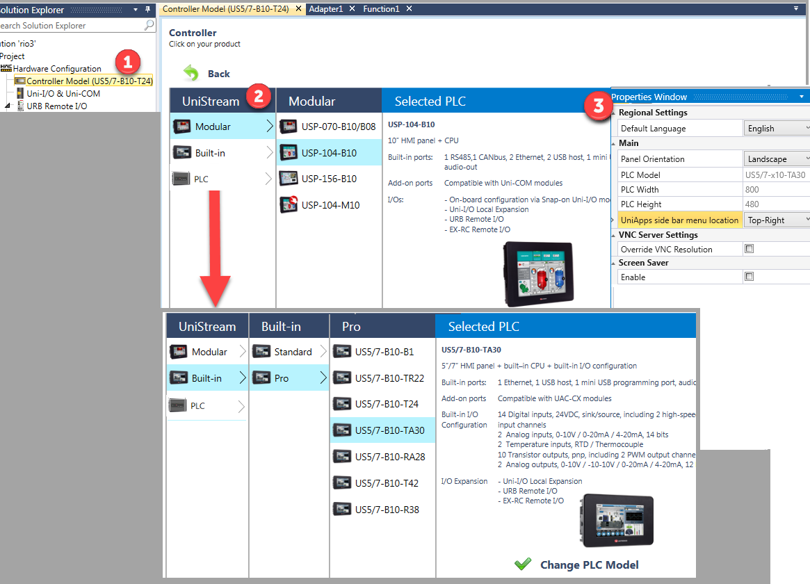
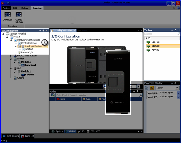
When you select your UniStream model in Hardware Configuration, only relevant options are available in UniLogic.
|
Differences between B10, B5, and B3
|
|
Feature
|
B10 Pro
|
B5 Standard
|
B3 Basic
|
|
I/O Expansion via Uni-I/O
|
Yes
|
No
|
|
Remote I/O Expansion via Ethernet I/O Adapter (URB)
|
Up to 8
|
1
|
|
VFD
|
32
|
2
|
|
MicroSD
|
Yes
|
No*
|
|
Add-on COM modules
|
3
|
2
|
|
System Memory
|
6GB
|
3GB
|
3GB
|
|
MODBUS Slaves
|
Unlimited
|
Up to 8
|
|
Ethernet/IP Scanners
|
16
|
1
|
|
Ethernet/IP Adapters
|
32
|
8
|
|
Web Server
|
Yes
|
No
|
No
|
|
SQL Client
|
Yes
|
No
|
No
|
|
MQTT
|
Yes
|
|
PID Loops
|
64
|
2
|
|
Data Sampler/Trends
|
Yes
|
No
|
|
CSV files: creating/ reading
|
Yes
|
No
|
|
FTP, server/client
|
Yes
|
No
|
|
Saving Data Tables to SD
|
Yes
|
No*
|
|
Screenshots
|
Yes
|
No
|
|
Sending email attachments
|
Yes
|
No
|
|
USB device (programming port)
|
Yes
|
No**
|
Note that in order to gain first-time access to a UniStream PLC out of the box, you must use the PLC's factory default IP.
|

|
UniStream PLC default IP
|
UniStream Light Panel default IP
|
|
IP: 192.168.1.4
Subnet mask: 255.255.255.0
Default Gateway: 192.168.1.1
|
IP: 192.168.1.5
Subnet mask: 255.255.255.0
Default Gateway: 192.168.1.1
|
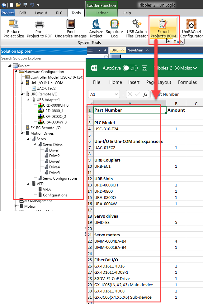
USB Action Files
This UniStream PLC feature enables the user to carry out certain task without the need to interact with the PLC via an HMI panel.
Programmers can create Action files in UniLogic and save them to a USB mass storage device, such as a flash drive. The end user can plug the drive into the PLC's USB port, and then press the Confirm button on the front of the PLC to run the file and execute the Actions. Actions include updating firmware and network settings, downloading applications, extracting log files and more and more.
|
Data
|
-
Read Data
Samples
-
Read Data
Tables
-
Read Retained
Memory
-
Write Retained
Memory
|
|
Logs
|
-
Read System
Logs
-
Read Alarms
Log
|
|
Updates
|
-
Update PLC
Application
-
Update Firmware
|
|
Communication
|
-
Read Network
Settings
-
Write Panel
IP
-
Write CPU
IP
-
Write DNS
Settings
|
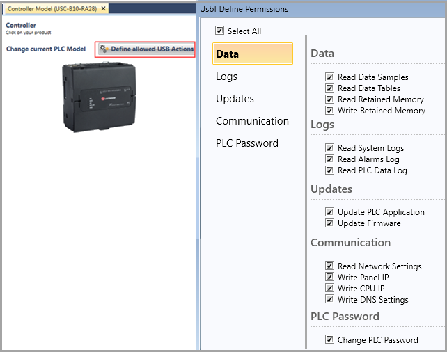
In order for Actions to execute, the PLC must have permission. USB Action Permissions are set in the UniLogic project, and are written to the PLC at download.
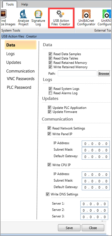
Set Permissions and Create the File
-
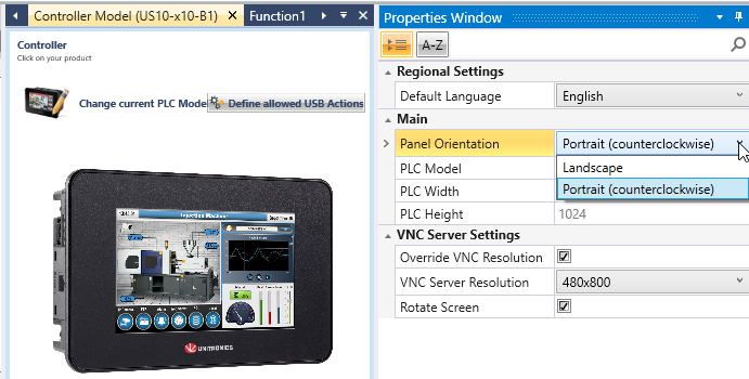
Set Permissions: in Hardware Configuration, click Define allowed USB Actions, and check the Actions you want to allow the PLC to execute.
-
Create the file: check all the desired Actions, and save the file.
|
Note
|
If you select Write Retained Memory, you need to browse to the location of the .hex file that contains the Write data. Do not rename this file.
|
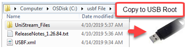
-
Copy all of the files that are created by the tool, and place them in the root folder of the USB storage drive.
Note that the USBF.xml file determines the Actions that will run.
|
|
|
|
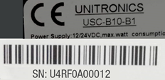
You can create Action files that are limited to run on a specific PLC, by renaming the USBF.xml file to include the PLC's serial number, found on a sticker on the PLC's side.
The accompanying image shows the serial number U4RF0A00012. Renaming a USBF.xml file as USBF_U4RF0A00012.xml will limit the files to run only on this PLC.
|
|
Executing the Action Files
 |
Confirm button: when the following instructions direct you to press the Confirm button, note that this means a simple, quick, press &release. Do not hold the button down.
|
-
Open the PLC's top door, and plug the USB drive into the PLC's USB port.
-
The PLC detects the USB drive, and checks the file; if the file is validated, the USB light turns a steady green.
-
Press the Confirm button on the front of the PLC to run the file and execute the Actions.
-
When the files starts running, the USB LED begins to blink, and blinks while the Actions are in progress.
-
Monitor the LED indications:
- If the Actions were executed successfully, the USB LED will be steady green. If the Actions require PLC reset, the RUN LED will blink green; press the Confirm button to restart the system.
- Note that after restart, the PLC will be in Run mode
- If the Actions did not execute successfully, the Error LED will also blink red; disconnect the USB drive to dismiss the error. See the Error section below.
Action Logs
The PLC creates a time stamped Action log folder on the USB root.
This folder contains:
- Files of data that have been read by the PLC; for example; the result of Read Network Settings will create a file
- An Action log file, showing how Actions were executed. Note that if an Action fails to execute, the PLC proceeds to the next Action.

Errors
If the USBF.xml file does not pass validation, the Error LED blinks red, and the PLC creates a time stamped log file on the root of the USB drive. An example, which assumes that the file was manually edited, is shown in the following image.
A complete table of LED indications is in the next section.

UniStream PLC LED Indications
The following tables summarize USB and Error indications.
| USB Actions LED Indications |
|
LED, Color & State
|
|
|
RUN
|
ERROR
|
USB
|
Indication
|
|
|
|
Green On
|
This LED turns steady green:
-
when a USB drive detected with valid Action file(s), indicating that you can press CONFIRM to begin running them.
-
when the files on the USB ran successfully.
|
|
|
|
Green blink
|
USB Action in progress.
|
|
Green blink
|
|
Green On
|
USB Action requires reset; press CONFIRM to restart system
|
|
|
Red blink
|
Off
|
USB drive detected, but contains corrupt Action file(s)
|
|
|
Red blink
|
Green ON
|
USB Action ran with error – disconnect the USB drive to dismiss the error.
|
|
LED Indications
|
|
I/O LEDs
|
Color
|
Indication
|
|
Digital Input
|
Green
|
Input state
|
|
Analog Input
|
Red
|
On: Input value is in Overflow
|
|
Relay and Transistor Output
|
Green
|
Output state
|
|
Status LEDs
|
Color & State
|
Indication
|
|
RUN
|
Green
|
On
|
Run mode
|
|
Blink
|
This indication is in conjunction with the USB LED.
See table below, USB Actions Indications, for details
|
|
Orange
|
On
|
Start-up mode
|
|
Blink
|
Stop mode
|
|
ERROR
|
Red
|
On/Blink
|
The Error LED can give indications in conjunction with the RUN and/or USB LED. See the next tables Error Indications and USB Actions Indications for details
|
|
USB
|
Green
|
On
|
A USB drive is detected that contains valid action file(s).
|
|
Blink
|
USB Action in progress
|
|
BATT. LOW
|
Red
|
On
|
Battery is low or missing
|
|
FORCE
|
Red
|
On
|
I/O Force on
|
|
Error Indications
|
LED, Color & State
|
|
|
|
RUN
|
ERROR
|
USB
|
Indication
|
|
|
|
Red blink
|
Off
|
One or more of the Actions in the USBF.xml file is corrupt – disconnect the USB drive to dismiss the error
|
|
|
|
Red blink
|
On
|
One or more of the Actions in the USBF.xml Action has failed – disconnect the USB drive to dismiss the error
|
|
|
|
Red blink
|
On
|
HW Configuration Mismatch – the HWC in the UniLogic application does not match the Uni-I/O modules physically connected to the PLC
|
|
|
Orange blink
|
Red blink
|
|
Application Invalid
or
Version Mismatch (UniLogic version is not supported by device firmware)
|
|
|
|
Red On
|
|
Uni-I/O Error (check wiring connections)
|
|
|
Orange blink
|
Red On
|
|
OS/Application error
|