![]()
This widget is available only on iMX6 platforms
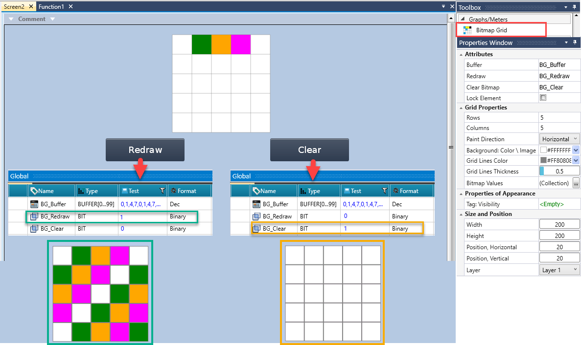
Use the Bitmap Grid widget to display a grid-based drawing area on the HMI, controlled by PLC data.
Each cell in the grid represents a single unit that can be painted with a color based on a buffer value. By writing values into the buffer and triggering a redraw, the PLC can draw, update, or clear graphical content on the HMI in a deterministic and repeatable manner.
|
|
This widget is available only on iMX6 platforms |
|
Bitmap Grid Attributes |
|
|
Tag: Buffer |
Select or create a buffer tag for the color data of the grid. Each byte in the buffer corresponds to one cell in the grid. |
| Tag: Redraw |
Link a bit tag. When the value changes from 0 to 1, the bitmap grid redraws itself based on the current buffer contents. |
|
Tag: Clear Bitmap |
Link a bit tag to trigger clearing the bitmap grid. When this bit is set to 1, all grid cells are cleared. |
|
Lock Element |
Check to prevent any adjustments or changes to the element's configuration. |
|
Grid Properties |
|
|
Rows |
Define the number of rows in the bitmap grid. |
|
Columns |
Define the number of columns in the bitmap grid. |
|
Paint Direction |
Determines how buffer values are mapped to grid cells.
|
|
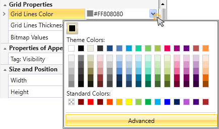
Grid Lines Color |
Click the drop-down arrow to select the color of the grid lines.
|
|
Grid Lines Thickness |
Define the thickness of the grid lines. |
|
Bitmap Values |
Bitmap Values enable defining which numeric values correspond to which colors. To configure the Values:
|