![]()
The UniStream Alarm system was designed according to the framework provided by the ISA (International Society of Automation) standard ANSI/ISA-18.2-2009, “Management of Alarm Systems for the Process Industries“
The UniStream Alarm system provides notifications of Alarms and events to the machine operator via a set of built-in HMI displays.
Typically, an Alarm display can:
Show Alarm status
Report the event to the machine operator
Provide instructions
Require operator action
Play an active role in the conditions enabling the running of the process
While the Alarms displays are on the screen, the PLC application continues to run. This includes both the Ladder and the HMI application.
|
|
The UniStream Alarm system was designed according to the framework provided by the ISA (International Society of Automation) standard ANSI/ISA-18.2-2009, “Management of Alarm Systems for the Process Industries“ |
This is a general description of the system components. Additional details are provided in the next sections of this topic.
Accessible from the Solution Explorer, this enables you to define Alarm groups and the Alarms within each group

When you create an Alarm, UniLogic creates an Alarms Status Struct to enable easier handling.

Alarm IndicatorAlarm Indicator
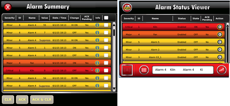
The indicator notifies the UniStream operator that an Alarm has occurred. By default, the alarm indicator is displayed as "Icon + Banner", meaning that it is a strip at the bottom of the screen that runs the width of the screen as shown in the following image. The banner comprises action buttons and a scrolling window showing active alarms.
Alarm indicator details, such as selecting which alarms appear in the scrolling window, indicator placement, "Icon only" banner display, and action buttons are detailed in the Alarm Indicator and Properties section of this topic.
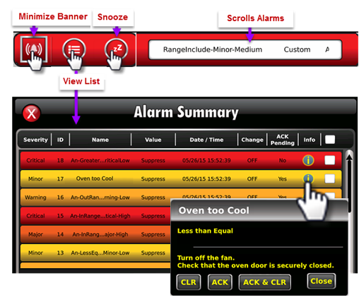
The summary list, shown in the above image, is automatically generated by the Alarm system. This is a list showing the status of the Alarms that are currently active in the Alarm system, and is a subset of the current Alarm Log.
The operator can:
Press the Info <i> icon of a specific Alarm to view the Alarm Description and Countermeasure instructions, and perform CLR, ACK, and ACK & CLR Actions
Filter the list of inactive Alarms by pressing the <i> icon and using the CLR, ACK, and ACK & CLR buttons.
The operator can select individual Alarms from the list, or all of the Alarms by checking the top row checkbox.
![]()
HMI Alarm Status ViewerHMI Alarm Status Viewer
The Alarm Status Viewer widget, located in the HMI Toolbox under Management, allows convenient Alarms management.
All of the Alarms defined in the system are listed here, along with their current status.
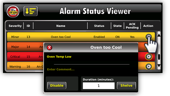
The manager can view Alarm status and enter Comments.
The manager may also suspend Alarm action via Disable and Shelve, detailed in the following table. Alarms can also be sorted according to Severity, Name, Alarm/Group and more.
|
|
Disable |
Shelve |
|
Description |
Completely disables an individual Alarm |
Temporarily disables an individual Alarm |
|
Will Alarm be listed in HMI Status Viewer? |
Yes. |
|
|
Will Alarm be listed in Alarm Summary? |
No |
No |
|
Will Alarm be logged to Alarm Log? |
No |
Yes |
|
Is the condition limited by time? |
No |
Yes |
|
Who defines the property? |
Operator in HMI Status Viewer |
Operator in HMI Status Viewer |
|
Note |
When the UniLogic project is edited and downloaded:
|
The system automatically logs Alarm events in the Alarm Log folder on the controller's SD card.
|
|
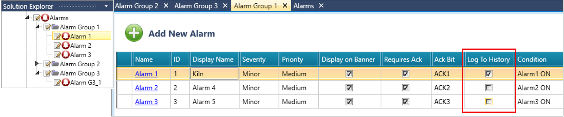
Deselect the Log To HistoryLog To History checkbox to prevent an alarm's events from being logged.
|
Log events are:
Alarm status changes (Condition trigger)
Operator Actions, such as Alarm Acknowledgment, Shelving/Unshelving, and Disabling/Enabling.
When the log reaches 10,000 rows, it is zipped and stored in the same folder. Note that the Zip Log button in the upper left Alarm Status Viewer shown in the above image allows the operator to force the current, active log to be zipped. The maximum number of rows in the current log is 1,024.
You can export the Alarm Log via FTP, as an email attachment, via WebServer, or via a DOK by transferring the data from the SD via UniApps or the HMI SD Browser widget.
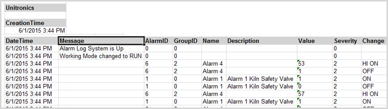
The log is in .xml format. Use the Unitronics Alarms Log to Excel Converter, a utility included with the UniStream Data Converters Suite available from the Unitronics website to convert the logs to Excel.
Disable, Shelve, SuppressDisable, Shelve, Suppress
These methods of disabling Alarms are summarized in the following table.
|
|
Disable |
Shelve |
Suppression (via bit tag) |
|
Description |
Completely disables an individual Alarm |
Temporarily disables the display of an individual Alarm (the Alarm remains active in the background) |
Completely disables an Alarm Group, controlled by Ladder. |
|
Will Alarm be listed in HMI Status Viewer? |
Yes. The Status column reflects whether the Alarm is Enabled, Disabled, Shelved, or Suppressed. |
||
|
Will Alarm be listed in Alarm Summary? |
No |
No |
No |
|
Will Alarm be logged to Alarm Log? |
No |
Yes |
No |
|
Is the condition limited by time? |
No |
Yes |
Can be, via Ladder |
|
Who defines the property? |
Operator in HMI Status Viewer |
Operator in HMI Status Viewer |
Programmer assigns bit in Alarm group properties. |
Alarm History WidgetAlarm History Widget
The Alarms History widget, located in the HMI Toolbox under Management, enables the user to view, but not edit, Alarms that have occurred.
Note that you can select Display Mode, either Default or Simple.
You can also select the Show Clear Button. This displays the CLR button shown in the next image; when pressed by the user, the rows displayed in the Alarm widget will be cleared.
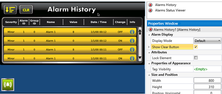
The user can also sort the Alarms.

This Ladder element, located in the Ladder toolbox under Alarms, enables you to acknowledge a single alarm, group of alarms, or all of the unacknowledged alarms in the system via Ladder.
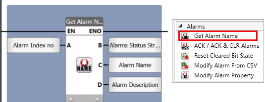
LF: Get Alarm NameLF: Get Alarm Name
Use this Ladder element to get the name and description of an Alarm, according to its index number.
|
|
Parameter Name |
Purpose |
|
A |
Alarm ID |
Enter a tag to provide the ID number of the Alarm, or assign a constant number |
|
B |
Status |
0 - In Progress, or Error 1 - Success |
|
C |
Alarm Name |
Assign a tag to hold the Alarm Name |
|
D |
Alarm Description |
Assign a tag to hold the Alarm Description |
LF: Reset Cleared Bit StateLF: Reset Cleared Bit State
This Ladder element, located in the Ladder toolbox under Alarms, enables you to reset the entire bit array, a specific bit, or the bits for an Alarm group.
LF: Modify Alarm From CSVLF: Modify Alarm From CSV
This Ladder element, located in the Ladder toolbox under Alarms, enables you to modify the alarm settings using a CSV file in the system via Ladder.
LF: Modify Alarm PropertyLF: Modify Alarm Property
This Ladder element, located in the Ladder toolbox under Alarms, enables you to modify the alarm properties in the system via Ladder.
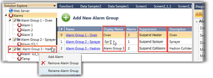
Select Alarms from the Solution Explorer and click Add New Alarm Group.
To edit the group name, right-click it on the Explorer and select Rename as shown in the next image.
Note that:
- In the Alarm Groups table, you can click and edit the Display Name, Description and assign an Alarm Suppression bit.
- The Properties Window defines the general properties for all Alarms.
- To improve panel performance and reduce memory consumption, limit the number of Alarm rows in both the Summary and History widgets, to a maximum of 32.
|
|
Use the Suppression bit in your Ladder program to disable the Alarm according to Ladder conditions. |
Edit the default general Alarm properties to suit your application.
|
Property
|
Purpose |
|
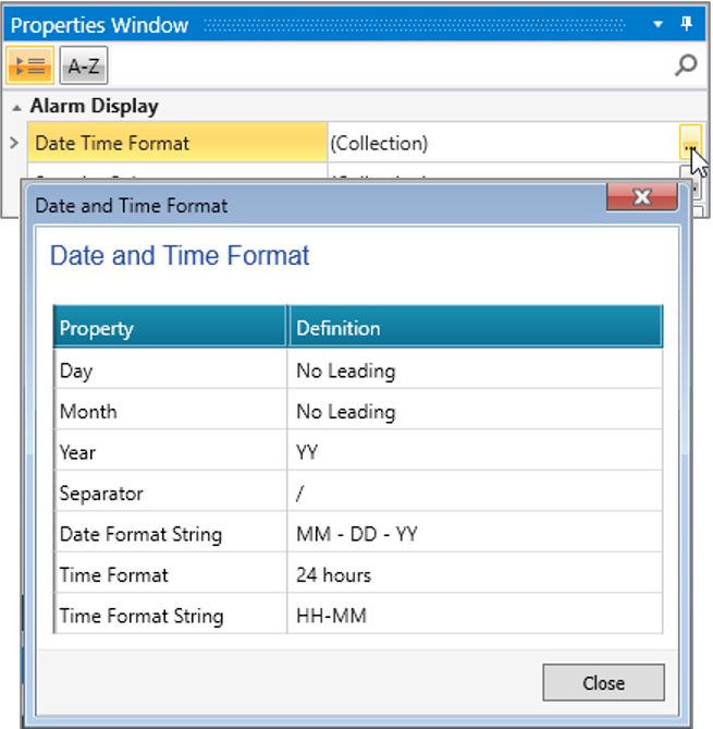
Date Time Format
|
This will provide the format for both the Alarm display and timestamp in the Alarm log.
|
|
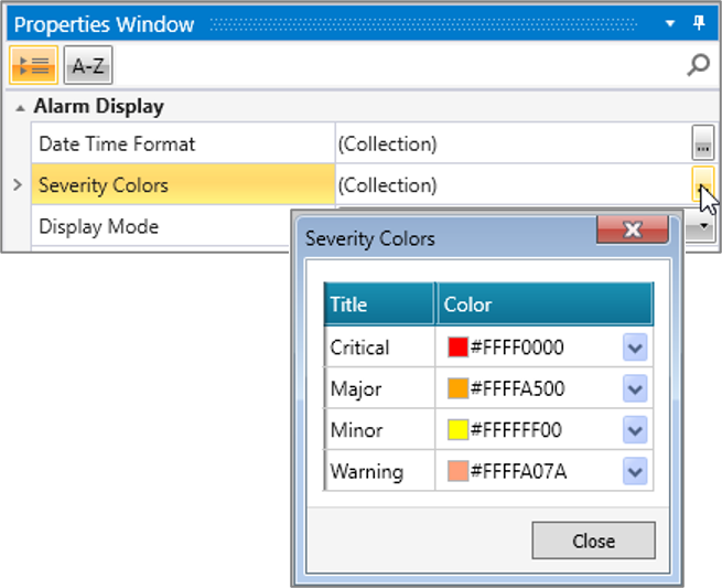
Severity Colors
|
These are the background colors for the Alarms display, both in the Alarms Summary and the Alarm Status Viewer widget.
|
|
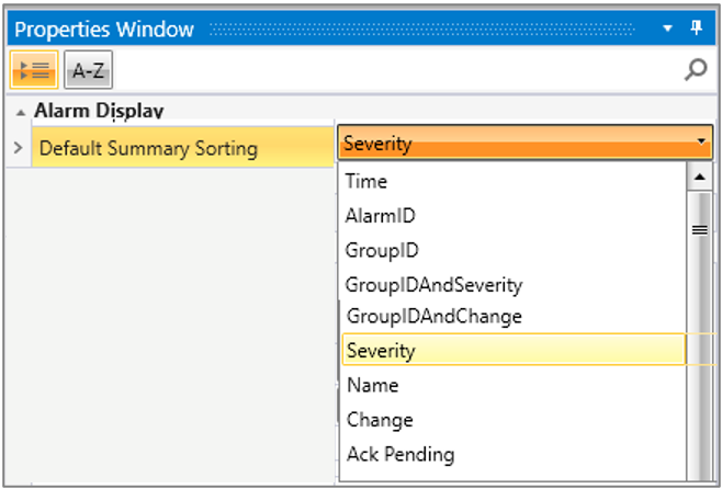
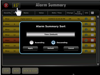
Default Summary Sorting |
This is where you can define the default sorting for the Alarm Summary list, according to Severity, Name, Alarm/Group, and more, to apply across the entire Alarms system.
|
|
Alarms Suppression |
You can choose to Suppress All Alarms for the entire system, by linking the Alarm's bit tag.
|
|
Alarm Indicator
|
This is where you define the Alarm Indicator properties for the entire Alarms system, as detailed in the Alarm Indicator section below.
|
|
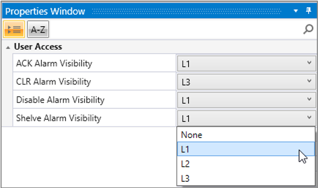
User Access
|
If you enable UAC, you can select if buttons--ACK, CLR, Disable and Shelve Alarm--will be visible to a specific User Group.
|
|
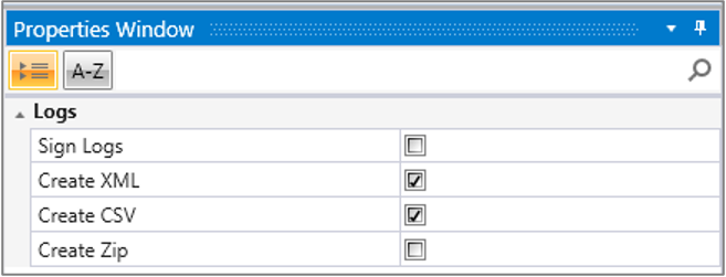
Logs |
You can select to create .xml, .csv, and .zip Alarm logs and sign them
|
The next image shows the Severity colors displayed for Critical, Major, and Minor Alarms.
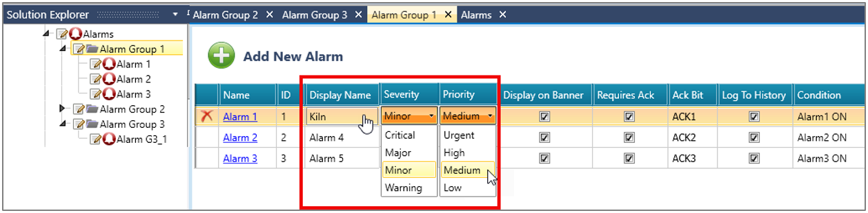
After you have defined a group of Alarms, click the Name to open the group, and click Add New Alarm.
To edit an Alarm group name, right-click it on the Explorer and select Rename.
Edit the default settings shown in the next image:
Click Display Name to change the default name. This name will identify the Alarm in both the Alarm Summary and the Alarm Status Viewer widget.
|
|
ID is a unique number assigned by the system. It cannot be edited or modified by the system. |
Edit Alarm Severity and Priority by clicking the fields and using the drop-down lists.
Severity determines the background color of the displayed Alarm.
Together, Severity and Priority affect the sort order of the Alarms in the Banner, Alarm Summary and the Alarm Status Viewer widget.
They are also recorded in the Alarm log file.
Use the checkboxes to determine whether the Alarm will be displayed in the banner of the scrolling window, will not be logged to the controller's SD card and Alarm History widget, and whether Ack is required. If Ack is required, click in the Ack bit field to assign a tag.
Click an individual Alarm to open it. The Alarm options are context-sensitive. The Condition you select, Digital or Analog, determines the options that are displayed.
Analog Alarms are accompanied by a graphic image to illustrate their function. Note that you can set a Deadband range around analog Alarm trigger values. Deadband is an Alarm attribute that sets a percentage of range around the value limits. The Alarm is inactive when the value being monitored as the Alarm Trigger in within this range. When the value crosses in or out of this range, the Alarm is triggered.
The purpose of the deadband is to eliminate nuisance Alarms.
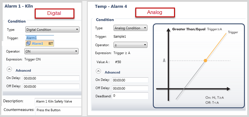
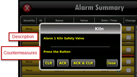
At the bottom of the Alarm window, you can add an Alarm Description and Countermeasure instructions for the operator.
These are displayed when the Alarm <i> icon is pressed in the Alarm Summary.
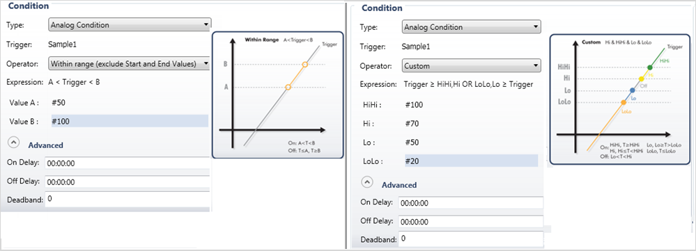
You can also create complex Analog Alarms, by selecting different Operators and setting range values.
When you select Operators, the number of values you can use as Alarm triggers varies accordingly.
For example, if you select the Operator such as Within Range, the interface changes so that you can set the range via Value A and Value B, as shown in the next image. If you select Custom, the interface presents 4 Values, in accordance with ISA guidelines:
High – indicates the High limit value. When the Tag value is equal to or greater than the Hi Limit value, the Hi limit alarm is generated.
HiHi - indicates the High High limit value. When the Tag value is equal to or greater than the HiHi Limit (Tag value is too high ) the HiHi limit alarm is generated.
Low - indicates the low limit value. When the Tag value is lower than or equal than the low Limit (Tag ) the low limit alarm is generated
LoLo - indicates the low low limit value. When the Tag value is lower than or equal than the LoLo Limit (Tag ) the LoLo limit alarm is generated.
The Deadband is used to detect that High High, High, Low, and Low Low alarm levels have returned to normal. A non-zero Deadband can reduce alarm condition chattering if the Triggering Tag value is continually changing but remaining near the level condition threshold.
The Deadband functions together with the these Operator conditions and the value limits. The Deadband value does not affect the transition to the “ON” (alarm active) state. Once a level condition is active, but before the condition will return to the “OFF” inactive (normal) state, the Tag value must either:
Drop below the threshold minus the deadband (for High and High High conditions).
OR
Rise above the threshold plus the deadband (for Low and Low Low conditions).
The Deadband is not used to condition the Minimum Duration time measurement.
For example:
If a Tag has a Hi Alarm limit of 80 and a Deadband Value of 5, UniStream will generate an Alarm when the Tag value is >= 80, the Alarm returns to “OFF” status when the Tag value returns to a value < 75.
If the Lo Alarm is set to 20, the Alarm will Activate when the Tag value is <=20. The Alarm will return to “OFF” state (normalized) when the Tag value returns to a value >25
|
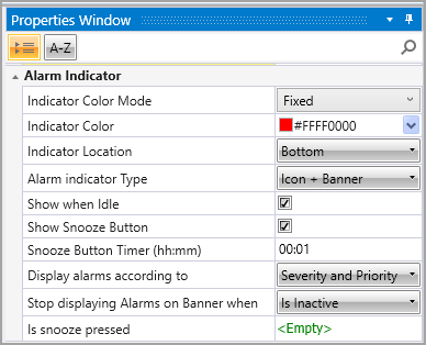
The Alarm Indicator section of the general Alarm properties determine if and how the Alarm Indicator is displayed. |
|
|
Property |
Purpose |
|
Indicator Color Mode |
Use the drop-down to assign a color option, Fixed, or by Highest Severity. |
|
Indicator Color |
Use the drop-down to change the default background color |
|
Indicator Location |
Select Top or Bottom. |
|
Alarm Indicator Type |
You can select
|
|
Show when Idle |
When enabled, the alarm will be visible, even if the device hasn't been actively used recently. |
|
Show Snooze Button |
Turns on when the user presses the Snooze button |
|
Snooze Button Timer |
This sets a time during which active alarms are not displayed in the scrolling window. When the user presses the Snooze button, the banner minimizes to the Icon only button mode. Note that this is only effective for an Alarm that has not changed state. If an alarm that was inactive becomes active, it will be displayed even if the Snooze is activated. |
|
Display Alarms According to |
You can select to sort Alarms in the scrolling window according to Severity and Priority (Default), Time, or by Group. |
|
Stop Displaying Alarms on Banner When |
You can stop Alarms from being displayed in the scrolling window if they are inactive (Default), have been acknowledged (Acked), or at Timeout (Selecting this allows you to set the time in minutes). |
|
Is Snooze Pressed? |
Link a bit that turns ON when Snooze button is pressed. |
Note that the user can change the location of the banner when it is displayed on screen from top to bottom and vice-versa, by pressing an area of the banner that is not occupied by a button for more than 2 seconds.
The Alarm interface of the Status Viewer and Alarms Summary has been translated into several Languages. Selecting a default language, for example French, translates the interface elements into French.
When the Alarm indicator runs at full size, it minimizes to a small green button when no Alarms are active. When an Alarm becomes active, the banner resumes its full size, as shown in the animation below.

The animation below demonstrates some of the Alarm indicator functions.