Information Mode

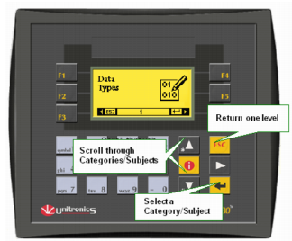
Information Mode is a utility that is embedded in the operating system of the controller. Via Information Mode, you can view data on the LCD screen, use the controller’s keyboard to directly edit data, and perform certain actions such as resetting the controller.  You can enter Information Mode at any time without regard to what is currently displayed on the LCD screen.

Viewing data does not affect the controller’s program. Performing actions, such as initializing the controller, can influence the program.


Note that when you use Information Mode, the keyboard is dedicated to that purpose. The keys return to normal application functions when you exit Information Mode.

Entering Information Mode

  1. To enter Information mode:
    -Non-touchscreen models: press the <i> key on the Vision’s keyboard.  
    -Touchscreen models: touch the screen in an area that is not occupied by a Keypad Entry variable or other screen object that has been assigned a Touch Property. Maintain contact for several seconds

  2. The controller enters Information Mode and requests a password.

  3. Enter your password.  The default password is 1111.  Note that at every power-up, this password is restored. To maintain a different password after power-up, use SB 2-Power-up as a condition to store the desired password value into SI 253.
    To change the password, access the controller via VisiLogic, then run On-line Test mode and changing the value. This value will be erased at power-up.

  4. The controller enters Information Mode, showing the first category, Data Types. Use the <Enter> key to enter a category.

  5. Press the <ESC> key to exit a category, and to exit Information mode.

The controller will block entry into Information mode until the correct password has been entered.  This is why you must record any password you set for your controller.

The data in Information Mode is arranged in Categories.  Each Category contains several Subjects. You navigate Information Mode by using the keyboard buttons.

To exit Information mode, press the <ESC>button on the Vision’s keyboard.  Each press returns one level up. Press the number of times necessary to exit.  

Notes

When you reenter Information Mode, the controller will return to the last Category viewed.


Info System Operands


The categories of available information depend on the controller model. The table below shows the basic categories of information.

Category

Subject

Possible Actions

Data Types

Memory Bits

  • View bit status


System Bits

  • Change bit status (Set/Reset)

Memory Integers


System Integers


Memory Longs


System Longs


Memory Double Words


System Double Words

  • View integer/long integer/double word value.


  • Change values


  • Toggle Base: view the value in decimal or hexadecimal form.

Inputs

  • View input status. ·

  • Force input status to 1 (FR1) or  0 (FR0).  Forced values stay in effect until Normal mode (NRM) is selected, or until the controller is initialized or reset.  
    Note
    Forced values do influence your program.  This can be useful in testing the effect of an input condition on an output status.

Outputs

  • View output status. ·

  • Force output status to 1 (FR1) or  0 (FR0).  Note that forced output values do not affect your program.

  • Set/Reset output status.

Timers

  • Enter a Preset Timer value.

  • View the current timer value and status by selecting the R.T. option.


TCP/IP (Standard Vision, Visible when Ethernet card is installed)

Enables you to view and edit IP address and socket settings.

System

Model & O/S Ver

  • Check the controller’s model number and operating system version.

  • Check whether the controller is in Run or Stop mode.


Working Mode

  • Check whether the controller is in Run or Stop mode.

  • Reset the controller. This restarts your program; restoring power-up values to all data types except for those protected by the battery backup. The battery protects Real Time Clock (RTC), all operand, and Data Table values.

  • Initialize the controller. This restarts your program and initializes all values, restoring 0 values to all data types.


Time & Date

  • View the Real Time Clock (RTC) settings.  Note that the RTC settings control all time-based functions.

  • Change the RTC settings via the controller’s keyboard.


Unit ID

The Unit ID number identifies a networked controller. You can:

  • Change the ID number.  The new ID number will remain in effect until the controller is reset.

  • Burn the ID number into the controller’s FLASH memory. This is a permanent change.


Serial Port 1

Serial Port 2

  • View and edit communication settings.

  • Select to Change or Burn the new settings.


Ethernet (Enhanced Vision, if an Ethernet card is installed)

Enables you to view and edit IP address, Socket settings, and other TCP/IP settings.


Monitor Communications
(Enhanced only)

This is a built-in communications 'sniffer'

  • Touch screen models: select Serial or Ethernet, then press Monitor. Note the button that allows you to toggle between Hex and ASCII

  • Non-touch screen models: Select Communication, then select Serial or Ethernet> COM Buffer. Use F2 to toggle between Hex and ASCII. In addition, press Enter, and then the Down key to toggle between. Tx and Rx.


CANbus

  • Built-in CANbus communications 'sniffer'

  • Change the CANbus baud rate.


Erase ALL PLC Data (V230 / V280 ONLY)

This completely erases all of the PLC's data,the OS, application, operand data, and Data Tables.

Note that after you select Erase All PLC Data, and confirm that you want to continue:

  1. The PLC enters bootstrap mode.

  2. A row of black boxes will appear at the bottom of the screen.
    At any point after the first box appears, press the Enter key.


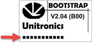
  3. A row of white boxes will appear above the black boxes.


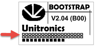
  4. Wait until an entire row has been completed, and a second one has begun to appear.

  5. Establish communications with the PLC, and download an OS.


Touchscreen (Touchscreen models only)

Enables you to calibrate the touchscreen, if it is not responding accurately to screen taps.

SD Card
(Enhanced Division)

Removable memory storage

Enables you to upload and download VisiLogic applications, OS firmware, and Data Table data from/to an SD card.

You can use these features to 'clone' a PLC application.

Function Block

Reserved for future use


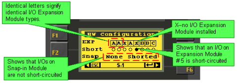
Hardware Configuration


  • Check if I/O Expansion Modules are installed.  Note that I/O Expansion Modules are represented by letters.  Identical module types are represented by identical letters as shown below.

  • Shows if an I/O module is short-circuited.