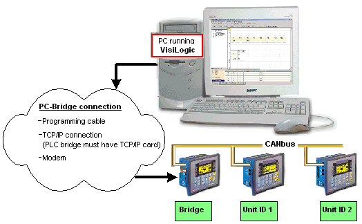
Use a PC to access controllers within a network either via a direct connection, TCP/IP connection, GSM or landline modem.

Connect your PC to any controller in the network using the programming cable supplied with the controller kit,
or via TCP/IP.

|
Note ♦ |
Different PCs can access a network at the same time, using different controller units as bridges. However, 2 different PCs cannot simultaneously access the same controller unit. |
|
♦ |
The PC accesses the bridge via a serial port. Vision controllers comprise three communication buffers. Note that if all three buffers are busy processing communications, new requests are ignored until a buffer is free. |
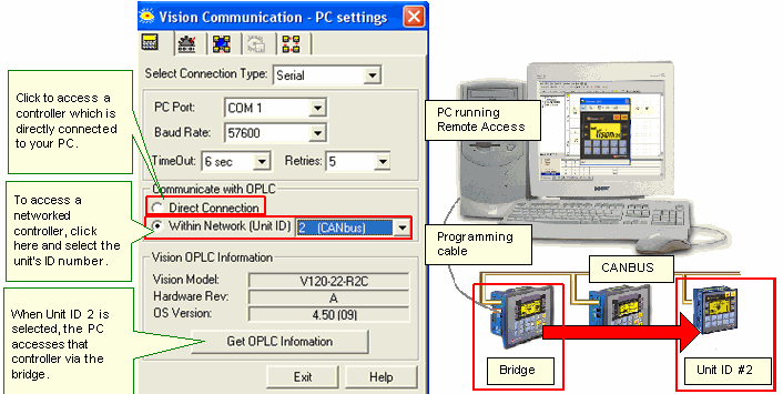
Select a networked controller by opening Communication & OS from the Connection menu, and then entering the Unit ID number.
|
Note ♦ |
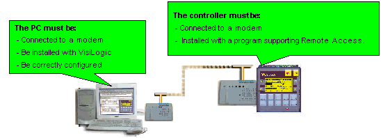
The PC-modem cable is not the same type of cable used to connect between the controller and the modem. Ensure that the cable used to connect the PC to the modem provides connection points for all of the modem's pins. |
|
♦ |
In order to ensure successful operations, it is recommended that you use an external PC modem. Internal modems may not support communications. |
|
♦ |
Both PC and controller must use the same type of modem: either landline or GSM. Internal PC modems must be used in conjunction with the driver provided by the modem's manufacturer. |
|
♦ |
If calls are routed via a switchboard, note that the switchboard settings may interfere with communications. Consult with your switchboard provider. |
The Unitronics’ cable provided with modem kits does not provide a standard connection. This connection is adapted to support the fact that Unitronics controllers do not support the control lines. The cable shorts the DSR and the DTR together, which ensures that the terminal is always ready to receive data.
For more information, refer to the topic Modem Connection and Pinouts.
Open PC Modem Configuration from the Connection>Modem Services menu.
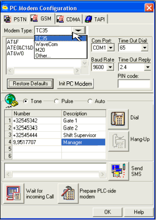
Note ♦ If, within the modem initialization strings, the parameter S7 TimeOut, is to short to permit the PLC's modem to answer, an error will result.
For example, if this parameter is set as S7=30, the PC modem will wait for 3 seconds to receive an answer from the PLC's modem. If, however, the PLC program's COM Init FB Answer Settings are set to 'Answer after 6 rings,' the PLC modem will not be able to answer before the 3 seconds have elapsed. In this case, the TimeOut parameter is exceeded, and the PC modem will return the No Carrier error.
You can run Online Test mode and use Remote Access session to display the networked controller on your PC screen.
To do this, click the Online Test button on the toolbar, then click the Remote Access button.
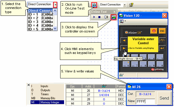
The controller model that is shown on the display is the one selected in Hardware Configuration.
During a Remote Access session, you can:
Use your cursor to operate the controller keypad and activate touch-screen objects (relevant models).
Use your PC keyboard to operate the controller keypad (numeric keys, function keys <F1> to <F8>). Note that the Vision <ESC> key is <E> on the PC keyboard, and that <F9> is reserved for activating Online mode.
Enter Information Mode by pressing the <i> key with your cursor.