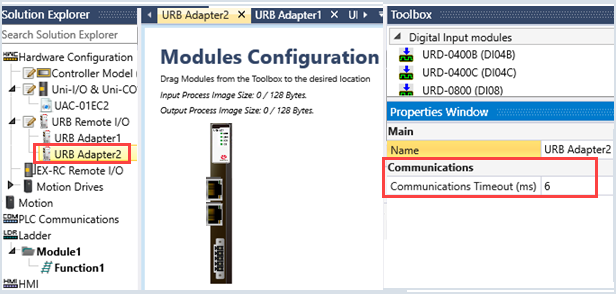
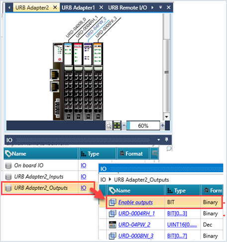
To add UniStream Remote I/O to your application, you add a URB adapter, and then add I/Os.
UniStream Remote I/Os comprise adapters and I/O modules that communicate via Ethernet, and via EtherCAT if supported by your controller model.
You can connect up to 8 Remote I/O adapters to a single UniStream. This includes all types of adapters; the maximum number of adapters per application is 8.
Ethernet adapters are displayed in Hardware Configuration. The type of adapter available for use in your project depends on the controller model you have selected in Hardware Configuration. Adapters available from Unitronics include:
URB-TCP, which can support up to 63 URB I/O modules per adapter
URB-TCP2, which can support up to 6 URB I/O modules per adapter
URB-EC1 (EtherCAT), which can support up to 16 URB I/O modules per adapter
However, note that the exact number of I/Os that can be included per adapter is dependent on the specific I/O connected to that specific adapter. For more information, refer to the Remote I/O user manual in the Unitronics Technical Library.
For further information, including the process data requirements of the I/Os, refer to the user guide for UniStream Remote I/Os, available in the Technical Library in the Unitronics website.
Adding UniStream Remote I/O
|
|
|
|
|
|
|
|
Note that before you can implement Remote I/Os, you should set the IP of the URB adapter.
Set URB Adapter Timeout, Reset URB AdapterSet URB Adapter Timeout, Reset URB Adapter
TCP Adapter Properties
Property |
Purpose |
IP Address |
Enter the IP of the Adapter |
Watchdog |
Check to enable the watchdog timer. If the adapter does not receive an answer from an I/O module within the defined Communication Timeout period, the watchdog activates. Timeout units: 1 unit=100msec Maximum units: 65535 |
Watchdog Recovery |
Select this enables the adapter to continue running after watchdog timeout and reset. |
Communications Timeout |
Units of milliseconds 2-250. The PLC sends a message 32 consecutive times, and waits for an answer. At each Send, the PLC places a value in the least significant bit of the struct tag URB Remote I/O Adapter Communication Global > Timeout Shift Register: 0 = Message Arrived /1 - Message did not arrive before the timeout.
|
Parameter Name |
Type |
Purpose |
Enable |
BIT |
Turn ON to enable or disable communications with the adapter |
Connected |
BIT |
I/O data exchange in progress |
Status |
UINT16 |
Operational State Reflects the connection status of the adapter. The order of connection events is:
If the process is successful, the status code progress to 6, IO Data Exchange in Progress, and remains there. If the process fails at any point, the controller will attempt to re-establish the connection. If troubleshooting is required, monitor the status codes to determine at which point the process fails : 0 - Establishing Connection (in Progress ) 1 - Sending Vendor ID 2- Number of Modules 3- Type of Modules 4- Modules Configurations 5- Adapter Configuration 6- IO Data Exchange in Progress 7 - Connection Disabled by User 8 - RIO Reset |
Vendor ID |
UINT16 |
|
Firmware Revision |
UINT16 |
|
Serial Number |
UINT16 |
|
Master Fault Action Option |
UINT16 |
|
Number of Expansion Modules |
UINT16 |
|
Current Connections |
UINT16 |
Parameter Name |
Type |
Purpose |
Communication Error Code |
UINT8 |
0 – OK Any other value, contact Support |
Adapter Internal Bus Status |
UINT16 |
MODBUS status |
Ethernet Interface Speed |
UINT16 |
Shows the Interface speed |
MAC Address |
Buffer (0-5) |
MAC address of the adapter |
IP Address |
UINT32 |
IP address of the adapter |
Watchdog Timeout |
UINT16 |
Shows the value defined in the Watchdog adapter property |
Watchdog Recovery Enabled |
BIT |
ON if the Watchdog Recover adapter property is selected |
Watchdog Error Counter |
UINT16 |
Shows the number of times the adapter's Watchdog activates |
Protocol Type |
UINT16 |
1 = UDP |
TX Message Counter |
UINT32 |
The number of messages sent by the PLC |
RX Message Counter |
UINT32 |
The number of messages received by the PLC |
Timeouts Counter |
UINT32 |
Faults Counter Increments when Timeout Shift Register =0xFFFFFFFF (all bits are ON) |
Timeout Shift Register |
UINT32 |
Internal Stability Check Each time the PLC sends a message, it shifts the number here (bitwise operation) by 1, and placed a value in the least significant bit. 0 = Message Arrived 1 - Message did not arrive before Communications Timeout |
Retries Counter |
UINT32 |
Internal Dropped Messages |
The URB adapter IP defaults are:
Default IP: 192.168.100.100
Subnet mask: 255.255.255.0
Note that on the adapter, there is a sticker showing its MAC address.
There are two methods of changing the IP address:
· Via UniLogic’s BOOTP Server
This is a utility accessible via the UniLogic ribbon
· Via DIP switch
These are physical switches on the adapter
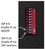
To enable the selected method, you must raise the appropriate DIP switch on the adapter. By factory default, the adapter is supplied with all switches down.
· Raise #9 to set IP via BOOTP Server:
-Enables the adapter BOOTP/DHCP
-The adapter sends 20 consecutive BOOTP/DHCP request messages every 2 seconds.
-If the BOOTP/DHCP server does not respond, the Adapter applies the latest
saved IP address
· Raise #10 to set IP via DIP switch:
You can then set the IP according to the description in the next table.
URB Adapter DIP Switches
# |
Role |
Description |
|
1 |
IP bit#0 |
Lowest IP Address octet when Switch #10=ON (raised) Example: XXX.XXX.XXX.IP |
|
2 |
IP bit#1 |
||
3 |
IP bit#2 |
||
4 |
IP bit#3 |
||
5 |
IP bit#4 |
||
6 |
IP bit#5 |
||
7 |
IP bit#6 |
||
8 |
IP bit#7 |
||
9 |
DHCP / BOOTP |
Enable DHCP / BOOTP |
|
10 |
Use DIP IP Value |
Enable IP Address set by DIP Switches |
Before you can set the IP address of the Remote IO adaptor via Unitronics BOOTP Server, you must raise DIP #9 (check that #10 is down)
1. Power OFF the URB adapter.
2. Raise DIP switch #9 to enable DHCP / BOOTP.
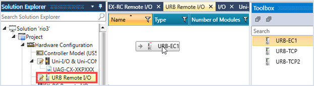
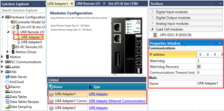
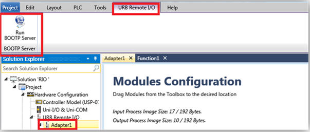
3. In UniLogic, in the Solution Explorer, select the adapter; the ribbon will open the tab URB Remote I/O.
4. On the ribbon, click on Run BOOTP Server to open the utility.
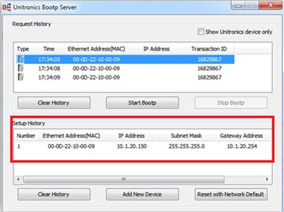
5. Click Start BootP in the Unitronics BOOTP Server; the upper section displays Ethernet devices that are in the network.
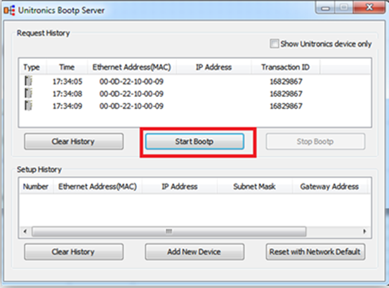
6. Power ON the URB adapter.
7. Locate the adapter’s MAC address and double-click on the row.
8. Enter the required IP address and select your PC Network card.
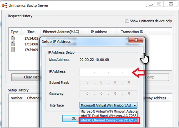
9. Click Ok. Now you should see the device in the bottom window including the IP address.
10. Power cycle the adapter; turn it off and on.
11. Use Ping from command line to check that the IP address is replying.
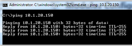
12. If the adapter replies successfully, then power off the adapter (URB-TCP/URB-TCP2 ) and lower DIP switch #9 (set to OFF).
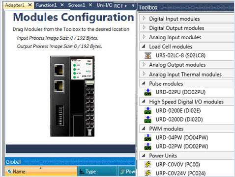
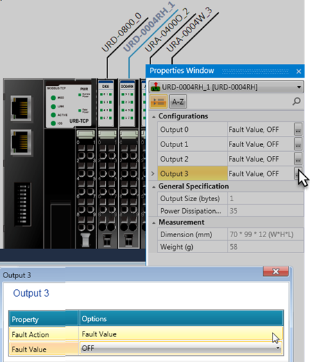
13. Configure the adapter and IO modules in UniLogic and test.
In order to use an EtherCAT adapter, you must first include an EtherCAT Master COM module in your project.
EtherCAT Master COM modules are compatible with UniStream PLC Standard and Pro models.
The EtherCAT Master COM module must be placed directly next to and connected to the CPU; it may be followed by other modules.
Only one EtherCAT Master COM module may be used per CPU.
An EtherCAT Master COM module can act as a motion controller to build the Motion Profile. The Master can can control up to 8 discrete axes, or up to 4 discrete axes and up to 4 cyclic synchronous axes.
When an axis is set to cyclic mode, the EtherCAT master generates the motion profile at every cycle.
Note that EtherCAT is managed via a System Struct.
|
|
|
|
Parameter Name |
Data Type |
|
|
Slave State |
UINT16 |
The 'State' variable holds the current EtherCAT state and link status of the EtherCAT slave device. 0x___1, Slave in 'INIT' state, 0x___2, Slave in 'PREOP' state, 0x___3, Slave in 'BOOT' state, 0x___4, Slave in 'SAFEOP' state, 0x___8, Slave in 'OP' state, 0x0010, Slave signals error, 0x0020, Invalid vendorId, productCode, 0x0100, Slave not present, 0x0200, Slave signals link error, 0x0400, Slave signals missing link, 0x0800, Slave signals unexpected link, 0x1000, Communication port |
|
Slave Error |
UINT16 |
Generated by UniLogic: 0x0 - Ok, 0x1 - Offline, 0x2 - Error EtherCAT state.. 0x4 - Not configured, 0x8 - Wrong configuration, 0x10 - Init command error, 0x20 - Mailbox init command error |
EtherCAT: Enabling Outputs As you add URB I/O modules, UniLogic adds a struct. Note that in order to write values to the physical URB outputs, you must turn ON the Enable Outputs bit in your application. |
![]() |
EtherCAT Master Module Struct
This is a system struct.
|
Parameter Name |
Data Type |
|
|
USB Flash Inserted |
BIT |
Is ON when there is a DOK in the modules USB port |
|
Module Connected |
BIT |
Turns ON when the module is physically connected to CPU |
|
Module Ready |
BIT |
Startup complete, Module is ready to start communication with the CPU |
|
Module Type |
UINT8 |
Value indicates Module type: 0 = UAC-02EC2 |
|
Initialization Status |
UINT32 |
Status indications: 0 = Not initialized 3 = Topology Mismatch: the order of the EtherCAT elements in the project' Hardware Configurations does not match the order in which they are physically connected to the controller 5 = Initialized successfully Other codes= Internal |
|
Current Firmware Version |
STRING-ASCII |
Indicates the firmware version currently installed in the module. |
|
Inserted Image Version |
STRING-ASCII |
Indicates the firmware version on the connected DOK |
|
Average cycles between diagnostics packages |
UINT32 |
Statistics |
|
Average time between diagnostics packages |
UINT32 |
Statistics |
|
PI Send Errors Count |
UINT32 |
Statistics |
|
PI Receive Errors Count |
UINT32 |
Statistics |
|
Wrong Working Counter Frames |
UINT32 |
Statistics |
|
Slave Response Time; |
UINT32 |
Statistics |
|
Light all LEDs up |
BIT |
Internal |
|
Average Cycle Time |
UINT32 |
Internal |
|
Min Cycle Time |
UINT32 |
Internal |
|
Max Cycle Time |
UINT32 |
Internal |
|
Communication Active |
BIT |
ON when communication between CPU and module is ok |
|
Diagnostics Mode |
BIT |
ON when module is in motion diagnostics mode |
|
Reserved |
UINT32f0...821 |
|
|
Master Bus OK |
BIT |
ON when Bus is OK |
|
Mandatory> slave is in wrong state |
BIT |
|
|
Mandatory slave is offline |
BIT |
|
|
Hot-connect slave is in wrong state |
BIT |
|
|
Hot-connect slave is offline |
BIT |
|
|
ViolationTimeCntr |
UINT32 |
Internal |
|
EtherCat master state |
UINT32 |
Internal |