UniLogic enables you to easily set up and exchange data with remote devices via EtherNet/IP.
You set up EtherNet/IP communications by entering parameters into a simple configuration grid. No ladder programming is required. Instead, you define the data tags that the UniStream controller will use to exchange data during an EtherNet/IP session, and you set a time interval (RPI) that determines the data exchange rate.
UniStream supports both implicit and explicit messaging implicit and explicit messaging.
Implicit
Messaging is also called “I/O” messaging. It is typically used
for real-time data exchange, where speed and low latency are important.
With Implicit Messaging, the two devices establish a “CIP connection”
and use it to exchange messages according to a predetermined trigger
mechanism, typically at a specified packet rate. In this method the
devices know and agree on the data formats they will use, the messages
include little information and thus the transmission is more efficient.
Explicit
Messaging follows
a request/reply (or client/server) format. Generally used to communicate
non-real-time data, this may be accomplished with or without prior
establishment of a CIP connection.
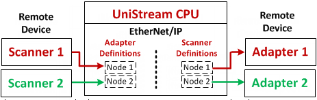
A single UniStream controller can function as both an:
EtherNet/IP I/O Scanner (Master/Originator/Client)
A scanner can originate (control) an EtherNet/IP session and can both read data from and write data to adapters.
EtherNet/IP I/O Adapter (Slave/Target/Server)
An adapter is a target, accessible to an Ethernet/IP scanner device. When UniStream is configured as an adapter, you determine which data tags may be accessed by a scanner.
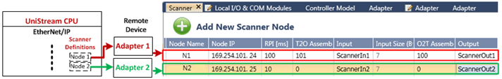
A single controller can contain multiple node definitions for both scanner and adapter, as shown in the next figure.
Each scanner node comprises data for the remote adapter it will access. This includes the IP address of the adapter, the RPI, the adapter's O2T and T2O Assembly Instance, and the data tags that UniStream will use to exchange data with the adapter. Note that multicast is supported. You can define up to 32 scanner nodes.
Each adapter node comprises the O2T and T2O Assembly Instance, and the data tags that UniStream will use to exchange data with the remote scanner. The scanner will access UniStream using the CPU IP address. You can define up to 16 adapter nodes.
|
Note that input/output data transfer is limited to 480 bytes maximum per session per node. |
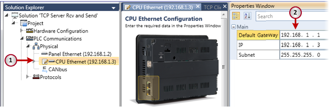
Before you begin working with EtherNet/IP, assign an IP address to the CPU.
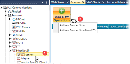
You can enable UniStream to function as a scanner to scan remote adapters.
In the Solution Explorer, under PLC Communications > Protocols, select Scanner.
In the Scanner window, under Add New Operation, click the drop-down arrow. Select:
-Add New Scanner Node if you want to enter parameters manually
-Add New Scanner Node from EDS if you want to import EDS parameters, and then navigate and select the EDS file.
After you import the EDS file, UniLogic automatically fills in the relevant parameters, and automatically creates input, output, and configuration structs to manage the remote adapter device data for use in your application.
In this case, you need to supply the parameters for the T2O and O2T Assembly, and for Configuration if required. This information should be included in the documentation of your adapter device.
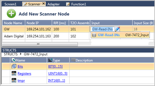
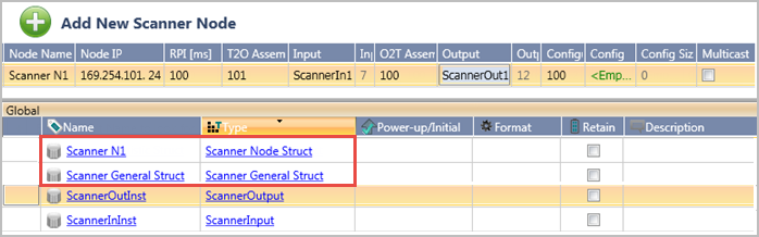
Click Add New Scanner Node.
UniLogic adds a row to hold the parameters of a remote adapter. Each row represents a different adapter.
Enter the appropriate parameters for the remote adapter that the scanner will access.
Remote Adapter Parameters
|
Name |
Definition |
|
Node Name |
This is a name that you assign to the node for your own reference. It has no function in the actual communications. |
|
Node IP |
Enter the IP address of the remote adapter. |
|
RPI (milliseconds) |
Enter the Requested Packet Interval. This determines the data exchange rate. The range is 1-32000. |
|
T2O Assembly Instance |
Enter the T2O parameter included in the documentation of the adapter device. T2O stands for Target to Originator. The direction of the message is from the adapter (target) to the scanner (originator). |
|
Input |
This holds the data the scanner reads from the adapter. |
|
Input Size |
Read-only. This shows the number of bytes linked to the Input. |
|
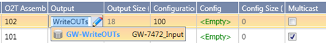
O2T Assembly Instance |
Enter the O2T parameter included in the documentation of the adapter device. O2Tstands for Originator to Target. The direction of the message is from the scanner (originator) to the adapter (target). |
|
Output |
This holds the data that the scanner writes to the adapter. |
|
Output Size |
Read-only. This shows the number of bytes linked to the Output. |
|
Configuration |
If your remote device requires Configuration, enter the parameter included in the documentation of the adapter device. |
|
Config |
Link tags, if your remote adapter requires Configuration. |
|
Config Size |
Read-only. This shows the number of bytes linked to the Configuration. |
|
Multicast |
Select this if your application requires Multicast. |
When you create a node, UniLogic creates three structs:
Scanner General struct
Holds properties for all scanner nodes in this application.
Scanner Node struct
Holds parameters for the specific node; UniLogic automatically creates a struct for each node (line) that you add.
Scanner Statistic struct
Internal use only.
General Struct
|
Name |
Data Type |
Definition |
|
CPU IP |
UINT32 |
Read-only. This is the address of the UniStream CPU. |
|
Initialization Status |
UINT32 |
0= Initialization is OK If there is a value other than 0, contact Support. |
|
Number of Nodes |
UINT32 |
Read-only. This is the number of nodes (rows) defined as EtherNet/IP scanners. |
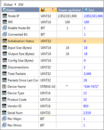
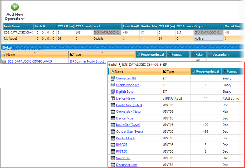
Scanner Node Struct
Note that you can use the Enable Node bit to prevent the scanner from communicating with the remote adapter.
|
Name |
Data Type |
Definition |
|
Node IP |
UINT32 |
This shows the IP address from the node's properties. |
|
RPI |
UINT16 |
This shows the Requested Packet Interval from the node's properties. |
|
Enable Node Bit |
Bit |
Use this in your application to control node communication. 0 = Disabled 1 = Enabled |
|
Connected Bit |
Bit |
This shows the actual connection state of the node. 0 = No connection 1 = Connected |
|
UINT32 |
0 - Idle 1 - Initializing Connection 2 - Trying to Open I/O Connection/ Ready for Explicit messaging 3 - Registering I/O Connection 4 - Opened I/O Connection 5 - Disconnecting 6 - Delay before attempting to reconnect 7 - Wrong Vendor ID |
|
|
Input Size (bytes) |
UINT16 |
Read-only. These show the data sizes entered in the node's properties. |
|
Output Size (bytes) |
UINT16 |
|
|
Config Size (bytes) |
UINT16 |
|
|
Total Packets |
UINT32 |
Read-only. This is the total number of packets received and sent between the scanner and this adapter. |
|
Packets Since Last Connect |
UINT21 |
Read-only. Contains the current number of packets sent during the current session. |
|
Connection Status |
UINT16 |
Contains the response status of the connection attempt. Click to view messages. |
|
Disconnections |
UINT32 |
Read-only. This is the total number of attempted sessions. |
|
Device Name |
String-ASCII |
These are the identifying parameters supplied by the remote adapter. |
|
Device Type |
UINT16 |
|
|
Product Code |
UINT16 |
|
|
Vendor ID |
UINT16 |
|
|
Serial Number |
UINT32 |
|
|
Rev Major (EIP) |
Bit |
|
|
Rev Minor (EIP) |
Bit |
|
The accompanying screenshot shows the struct in online Test Mode, displaying node definition values, node status, and values read from the adapter such as Device Name, Type, Product Code, and Vendor ID. |
|
To configure UniStream to function as an adapter, you define nodes and include data tags that you want a remote EtherNet/IP scanner to access.
|
|
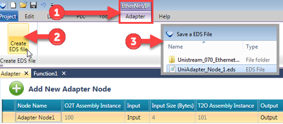
Note that once you have defined a node, you can create an EDS file for the node and export it for use with an adapter. |
In the Solution Explorer, under PLC Communications > Protocols, select Adapter under PLC Communications > Protocols, select Adapter.

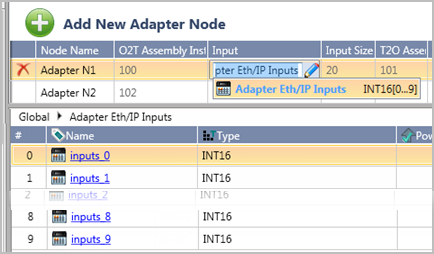
Click Add New Adapter Node.
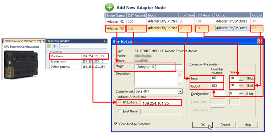
UniLogic adds a row to hold the adapter parameters, including the specific Input and Output data tags to be accessed by remote EtherNet/IP scanners. Each row represents a different adapter.
Enter the appropriate parameters.

Adapter Parameters
|
Name |
Definition |
|
Node Name |
This is a name that you assign to the node for your own reference. It has no function in the actual communications. |
|
O2T Assembly Instance |
Read-only. This parameter is automatically assigned by UniLogic. |
|
Input |
This will hold the data that a scanner can read. You can use data tags such as buffer and array. |
|
Input Size |
Read-only. This shows the number of bytes you allocate to Input. |
|
T2O Assembly Instance |
Read-only. This parameter is automatically assigned by UniLogic. |
|
Output |
This will hold the data that the scanner writes to the adapter |
|
Output Size |
Read-only. This shows the number of bytes linked to the Output. |
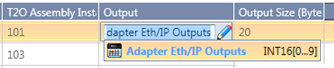
The screenshot below shows how to use these parameters to configure RSLogix 5000 to enable a scanner to access a UniLogic adapter.
 |
In UniLogic, the parameter Size is given in bytes. Allow for this if your scanner device uses integers. |
When you create a node, UniLogic creates three structs:
Adapter General struct
Holds properties for all adapter nodes in this application.
Adapter Node struct
Holds parameters for the specific node; UniLogic automatically creates a struct for each node (line) that you add.
Adapter Statistic struct
Internal use only.

General Struct
|
Name |
Data Type |
Definition |
|
CPU IP |
UINT32 |
Read-only. This is the address of the UniStream CPU. |
|
Initialization Status |
UINT32 |
0= Initialization is OK If there is a value other than 0, contact Support |
|
Number of Nodes |
UINT32 |
Read-only. This is the number of nodes (rows) defined as EtherNet/IP scanners. |
|
Explicit Message Count |
UINT16 |
If you are implementing Explicit messaging, this is the number of Explicit messages in the queue. |
|
Explicit Busy |
BIT |
Adapter Node Struct
|
Name |
Data Type |
Definition |
|
Initialization status |
UINT32 |
0 - Idle 1 - Initializing Connection 2 - Trying to Open I/O Connection 3 - Registering I/O Connection 4 - Opened I/O Connection 5 - Disconnecting 6 - Delay before attempting to reconnect |
|
Connected Bit |
Bit |
This shows the actual connection state of the node. 0 = No connection 1 = Connected |
|
Input Size (bytes) |
UINT16 |
These show the data sizes entered in the node's properties |
|
Output Size (bytes) |
UINT16 |
|
|
Config Size (bytes) |
UINT16 |
|
|
Total Packets |
UINT32 |
This is the total number of packets received and sent between the scanner and this adapter |
|
Packets Since Last Connect |
UINT21 |
Contains the current number of packets sent during the current session |
|
Disconnections |
UINT32 |
This is the total number of attempted sessions |
|
To create and export an EDS file for a defined an adapter node:
|
|
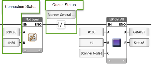
UniStream supports Explicit Messaging with third-party devices as both Scanner and Adapter. UniLogic enables you to implement Scanner functionality via Ladder functions, and supports Adapter functionality by allowing you to define structs to enable Vendor-specific Objects to access the requested data.
The following Ladder functions enable the controller to initiate request/response oriented data exchange with the remote devices that you have defined under Ethernet/IP Scanner.
|
Notes |
|
Get Attribute All
|
|
Parameter Name |
Purpose |
|
A |
Class |
This is the class of the Object to which the explicit message is sent. |
|
B |
Instance |
This number is the instance of the class that will receive the message/ |
|
C |
Scanner Node |
This is the name of the destination node, as defined in Protocols>EtherNet/IP>Scanner. |
|
D |
Destination |
This is where the data received from the remote object will be written in UniStream/ |
|
E |
Status |
Supports the standard EtherNet/IP message codes. |
Get Attribute Single
|
|
Parameter Name |
Purpose |
|
A |
Class |
This is the class of the Object to which the explicit message is sent. |
|
B |
Instance |
This number is the instance of the class that will receive the message. |
|
C |
Attribute |
Defines which attribute of the instance is being accessed. |
|
|
Scanner Node |
This is the name of the destination node, as defined in Protocols>EtherNet/IP>Scanner. |
|
D |
Destination |
This is where the data received from the remote object will be written in UniStream. |
|
E |
Status |
Supports the standard EtherNet/IP message codes. |
Get Attribute Single to Buffer
This enables you to access the remote data and write it to a buffer within UniStream.
|
|
Parameter Name |
Purpose |
|
A |
Class |
This is the class of the Object to which the explicit message is sent. |
|
B |
Instance |
This number is the instance of the class that will receive the message. |
|
C |
Attribute |
Defines which attribute of the instance is being accessed. |
|
|
Scanner Node |
This is the name of the destination node, as defined in Protocols>EtherNet/IP>Scanner. |
|
D |
Destination |
This is where the data received from the remote object will be written in UniStream. |
|
E |
Offset in Bytes |
This offset determines the start point: where the data will be written in the buffer, |
|
F |
Destination Buffer |
The name of the buffer to which the data will be written |
|
G |
Status |
Supports the standard EtherNet/IP message codes. |
|
H |
Bytes Received |
The number of bytes written to the buffer |
Set Attribute All
|
|
Parameter Name |
Purpose |
|
A |
Source |
The data tag in UniStream containing the data to write to the remote Object. The entire contents of the tag will be sent, regardless of length. |
|
B |
Class |
This is the class of the Object to which the explicit message is sent. |
|
C |
Instance |
This number is the instance of the class that will receive the message/ |
|
D |
Scanner Node |
This is the name of the destination node, as defined in Protocols>EtherNet/IP>Scanner. |
|
E |
Status |
Supports the standard EtherNet/IP message codes. |
Set Attribute Single
|
|
Parameter Name |
Purpose |
|
A |
Source |
The data tag in UniStream containing the data to write to the remote Object. The entire contents of the tag will be sent, regardless of length. |
|
B |
Class |
This is the class of the Object to which the explicit message is sent. |
|
C |
Instance |
This number is the instance of the class that will receive the message. |
|
|
Attribute |
Defines which attribute of the instance is being accessed. |
|
D |
Scanner Node |
This is the name of the destination node, as defined in Protocols>EtherNet/IP>Scanner. |
|
E |
Destination |
This is where the data received from the remote object will be written in UniStream. |
|
|
Status |
Supports the standard EtherNet/IP message codes. |
Set Attribute Single to Buffer
This enables you to select and copy data from a Buffer in UniStream by via an Offset and Number of bytes to copy, and to write the data to the remote device.
|
|
Parameter Name |
Purpose |
|
A |
Source |
The data tag in UniStream containing the data to write to the remote Object. |
|
B |
Class |
This is the class of the Object to which the explicit message is sent. |
|
C |
Instance |
This number is the instance of the class that will receive the message. |
|
D |
Attribute |
Defines which attribute of the instance is being accessed. |
|
E |
Scanner Node |
This is the name of the destination node, as defined in Protocols>EtherNet/IP>Scanner. |
|
F |
Offset in Bytes |
This offset determines the start point: from where the buffer data will be copied. |
|
G |
Bytes to Copy |
This is the number of bytes that will be copied from the buffer. |
|
H |
Status |
Supports the standard EtherNet/IP message codes. |
Via explicit messaging, any EtherNet/IP scanner can access a UniStream controller and access data tags that are defined in Vendor Specific Objects.
To define these objects:
Create a struct that accords to your Vendor's Object.
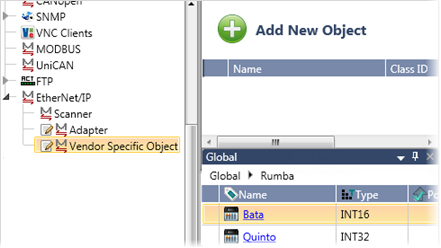
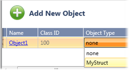
Under EtherNet/IP>Vendor Specific Objects, click Add New Object, and under Object Type, select the struct.
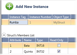
Click the Name of the Object to open it, and then click Add New Instance.
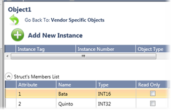
Create the instance by selecting the desired struct.
Note that, in an instance. you can set the struct members to read-only.
This data is now available for any EtherNet/IP scanner to access via Explicit Messaging.
Note that the codes prefixed with "ENIP + IN_PROGRESS " are UniStream codes, and are not part of the EtherNet/IP protocol.
|
ERR_SUCCESS |
0x00 |
|
ERR_STORE_FAILURE |
0x19 |
|
ERR_CNXN_FAILURE |
0x01 |
|
ERR_ROUTE_REQ_TOO_LRG |
0x1A |
|
ERR_RESOURCE_UNAVAIL |
0x02 |
|
ERR_ROUTE_RSP_TOO_LRG |
0x1B |
|
ERR_INV_PARAMNAME |
0x03 |
|
ERR_MISSING_ATTR_LIST |
0x1C |
|
ERR_PATHSEGMENT |
0x04 |
|
ERR_INV_ATTR_LIST |
0x1D |
|
ERR_PATHDESTUNKNOWN |
0x05 |
|
ERR_EMBEDDED_SERV_ERR |
0x1E |
|
ERR_PARTIALXFER |
0x06 |
|
ERR_VENDOR_SPECIFIC |
0x1F |
|
ERR_CNXNLOST |
0x07 |
|
ERR_INV_SERVICE_PARM |
0x20 |
|
ERR_SERV_UNSUPP |
0x08 |
|
ERR_WO_VAL_ALREADY_W |
0x21 |
|
ERR_INV_ATTRIBVAL |
0x09 |
|
ERR_INV_REP_RECV |
0x22 |
|
ERR_ATTR_LIST_ERR |
0x0A |
|
ERR_BUFFER_OVERFLOW |
0x23 |
|
ERR_IN_REQ_STATE |
0x0B |
|
ERR_MSG_FORMAT_ERR |
0x24 |
|
ERR_OBJ_STATE_CONFLICT |
0x0C |
|
ERR_KEY_ERR_IN_PATH |
0x25 |
|
ERR_OBJ_ALREADY_EXISTS |
0x0D |
|
ERR_PATH_SIZE_INV |
0x26 |
|
ERR_ATTR_READONLY |
0x0E |
|
ERR_UNEXP_ATTR_IN_LIST |
0x27 |
|
ERR_PRIV_VIOLATION |
0x0F |
|
ERR_INV_MEMBER_ID |
0x28 |
|
ERR_DEV_STATE_CONFLICT |
0x10 |
|
ERR_MEMBER_READONLY |
0x29 |
|
ERR_REPLY_SIZE |
0x11 |
|
ERR_G2ONLY_GEN_ERR |
0x2A |
|
ERR_FRAG_PRIM_VAL |
0x12 |
|
ERR_UNKNOWN_MB_ERR |
0x2B |
|
ERR_INSUFF_DATA |
0x13 |
|
ERR_ATTR_NOT_GETTABLE |
0x2C |
|
ERR_ATTR_UNSUPP |
0x14 |
|
IN_PROGRESS |
0x30 |
|
ERR_TOOMUCH_DATA |
0x15 |
|
ENIP_BUSY |
-1 |
|
ERR_UNEXISTANT_OBJ |
0x16 |
|
ENIP_QUEUE_ERROR |
-2 |
|
ERR_SERV_FRAG_SEQ |
0x17 |
|
ENIP_TIMEOUT_ERROR |
-3 |
|
ERR_NO_ATTR_DATA |
0x18 |
|
ENIP_WRONG_OFFSET |
-4 |
|
|
|
|
ENIP_DATAOVERFLOW |
-5 |
|
ENIP_NODE_DISABLED |
-6 |