UniLogic supports key IEC 61131-3 function blocks directly in the ST editor, including bistables, edge detection, counters, timers, and RTC blocks.
These are stateful blocks; they maintain internal data across scan cycles, unlike simple one-shot functions. All blocks must be declared as instances.
A bistable latch remembers its state; once set, it stays set until explicitly reset, even if the trigger that set it is no longer active. This makes bistable blocks ideal for:
Motor run/stop control - press Start to latch ON, press Stop to latch OFF
Alarm latching - latch an alarm TRUE when a fault occurs, clear it only when acknowledged
Mode selection - hold a machine in a state until a condition explicitly changes it
Two types are available. The difference is only in what happens if both inputs are TRUE at the same time:
|
Block |
Dominant Input |
Wins when both S and R are TRUE |
|
RS |
R (Reset) |
Q becomes FALSE - Stop always wins. |
|
SR |
S (Set) |
Q becomes TRUE - Start always wins. |
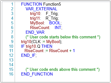
These function blocks detect signal transitions and fire a single-cycle pulse on the output Q.
R_TRIG (Rising Edge) - Pulse when CLK transitions from 0 -> 1
F_TRIG (Falling Edge) - Pulse when CLK transitions from 1 -> 0
Declaration and Usage
|
Q is a Read-only output member. CLK is the Hidden input member. |
Counters track events based on signal transitions.
CTU - Count Up
Counts up from 0 to a preset value.
|
Property |
Type |
Access |
Description |
|
CU |
BIT |
Input (Hidden) |
Count-up trigger. A rising edge increments the counter value CV by 1 |
|
R |
BIT |
Input (Hidden) |
Resets the output Q and the counter value CV |
|
PV |
INT |
Input (Hidden) |
The counter limit value |
|
Q |
BIT |
Read-only output |
Set to TRUE when the counter value CV reaches PV |
|
CV |
INT |
Read-only output |
The current count value |
Declaration and Usage example:
|
VAR |
CTD - Count Down
Counts down from a preset value to 0.
|
Property |
Type |
Access |
Description |
|
CD |
BIT |
Input (Hidden) |
Count-down trigger. A rising edge decrements the counter value CV by 1 |
|
LD |
BIT |
Input (Hidden) |
Load preset value |
|
PV |
INT |
Input (Hidden) |
The counter limit value |
|
Q |
BIT |
Read-only output |
Set to TRUE when the counter value CV reaches PV |
|
CV |
INT |
Read-only output |
The current count value |
Declaration and Usage example:
|
VAR
|
CTUD - Count Up/Down
Counts upward on rising edges of CU and downward on rising edges of CD.
|
Property |
Type |
Access |
Description |
|
CU |
BIT |
Input (Hidden) |
Count-up trigger. Increments the counter on a rising edge |
|
CD |
BIT |
Input (Hidden) |
Count-down trigger. Decrements the counter on a rising edge |
|
R |
BIT |
Input (Hidden) |
Resets the counter to 0 |
|
LD |
BIT |
Input (Hidden) |
Load preset value |
|
PV |
INT |
Input (Hidden) |
Preset value |
|
QU |
BIT |
Read-only output |
TRUE when CV >= PV |
|
QD |
BIT |
Read-only output |
TRUE when CV <= 0 |
|
CV |
INT |
Read-only output |
The current count value |
Declaration and Usage example:
|
VAR
|
|
UniLogic supports three IEC-standard timer function blocks.
|
Function Block |
Name |
Description |
|
TON |
Timer ON-Delay |
Delays turning an output ON |
|
TOF |
Timer OFF-Delay |
Delays turning an output OFF |
|
TP |
Timer Pulse |
Generates a fixed-duration output pulse |
|
Legacy timer implementations (from previous UniLogic versions) have been renamed with the _UNI_suffix: TON_UNI_, TOF_UNI_, TP_UNI_, TA_UNI_, TE_UNI_, and TIMER_RESET. |
TIME Data Type
The PT and ET properties use the TIME data type. For full details on TIME literals, supported units, syntax rules, and valid ranges, see Time Literals.
TIME literal examples:
|
T#5s (* 5 seconds *) T#2m30s (* 2 minutes and 30 seconds *) T#1h15m20s (* 1 hour, 15 minutes, 20 seconds *) TIME#500ms (* 500 milliseconds, alternative prefix *) |
IEC Function Block Structure
All three timer types share a common structure:
|
Property |
Type |
Access |
Description |
|
IN |
BIT |
Input (Hidden) |
Control input. Rising edge or level triggers the timer depending on type |
|
PT |
TIME |
Input (Hidden) |
Preset time. The target duration |
|
Q |
BIT |
Read-only output |
Timer output. Meaning depends on timer type |
|
ET |
TIME |
Read-only output |
Elapsed time. Counts up from 0 to PT while the timer is active |
Declaring IEC Timers
|
VAR T1 : TON; T2 : TOF; T3 : TP; END_VAR |
TON - On-Delay Timer
Use TON to delay turning an output ON. The output Q becomes TRUE only after the input IN has been continuously TRUE for the preset duration PT.
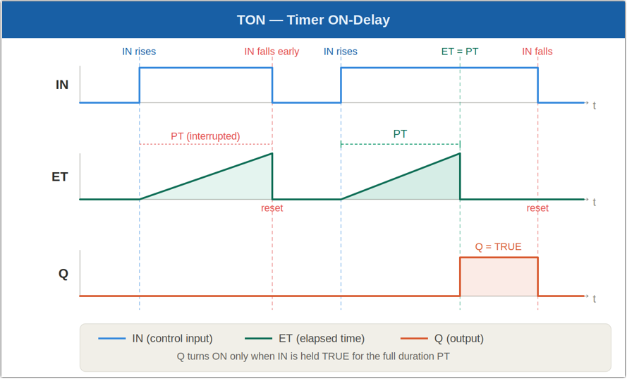
Behavior:
When IN becomes TRUE:
The timer starts counting (ET increments from 0)
When ET >= PT, Q becomes TRUE
When IN becomes FALSE before ET reaches PT:
The timer resets: ET = 0
Q remain FALSE
Usage example:
|
T1(IN := StartSignal, PT := T#5s); Motor := T1.Q; (* Motor starts 5 s after StartSignal rises *) |
TOF - Off-Delay Timer
Use TOF to delay turning an output OFF. The output Q becomes TRUE immediately when IN rises, then becomes FALSE after IN has been FALSE for the preset duration PT.
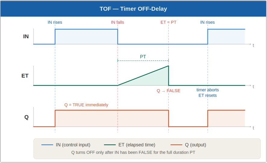
Behavior:
When IN = TRUE:
Q = TRUE immediately
ET remains 0
When IN becomes FALSE:
The timer starts counting (ET increments from 0)
Q remains TRUE while the timer runs
After PT has elapsed, Q becomes FALSE
If IN rises again while the timer is running:
The timer stops and resets (ET = 0)
Q remains TRUE
Usage example:
|
T2(IN := RunSignal, PT := T#3s); Valve := T2.Q; (* Valve stays open 3 s after RunSignal falls *) |
TP - Pulse Timer
Use TP to generate a fixed-duration output pulse. On a rising edge of IN, Q becomes TRUE and stays TRUE for exactly PT, regardless of the subsequent state of IN.
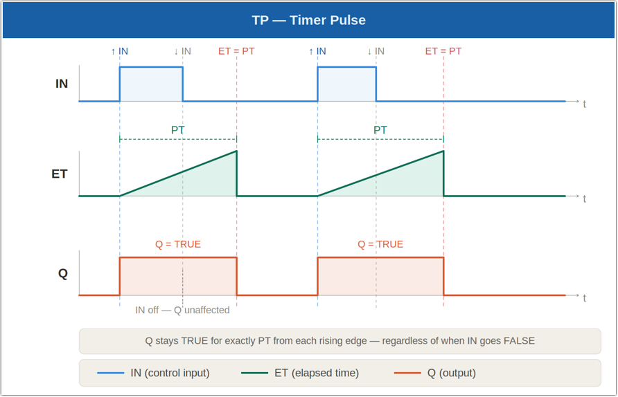
Behavior:
On a rising edge of IN:
Q becomes TRUE immediately
ET starts counting from 0
While the timer is running (ET < PT):
Q remains TRUE regardless of IN state
A new rising edge on IN has no effect
When ET reaches PT:
Q becomes FALSE
ET resets to 0
Usage example:
|
T3(IN := Trigger, PT := T#500ms); Buzzer := T3.Q; (* Buzzer sounds for exactly 500 ms per trigger *) |
The RTC function block maintains a continuously increasing DATE_AND_TIME value starting from a preset timestamp.
Unlike elapsed-time calculations, the CDT value represents an absolute timestamp that advances while the block is enabled.
RTC Structure
|
Property |
Type |
Access |
Description |
|
EN |
BIT |
Input (Hidden) |
Enables the RTC block |
|
PDT |
DATE_AND_TIME |
Input (Hidden) |
Preset date and time |
|
Q |
BIT |
Read-only output |
TRUE while the RTC is counting |
|
CDT |
DATE_AND_TIME |
Read-only output |
Current date and time value |
Declaration and Usage Example:
|
VAR |