![]()
The following sections are applicable only to Unitronics VFDs, and are not applicable to VFDs from other manufacturers.
Unitronics VFDs work seamlessly with UniStream, as well as with Vision and Samba controllers.
Communicating via Modbus RTU , they are general purpose VFDs, available as single and three phase, from 0.4 kW up to 110 kW.
You can use UniLogic to configure and operate up to 32 Unitronics VFDs via Ladder, or directly from UniStream's HMI panel.
To use Unitronics VFDs in your application you must:
Configure the Serial Port as VFD
Add VFDs to your Hardware Configuration.
UniLogic creates a supporting struct for each VFD.
Configure the VFD. You can:
-create and edit a Configuration file in UniLogic,
-upload a Configuration file from a VFD and edit it as necessary,
-export a Configuration file from UniLogic, edit it, and import it into UniLogic.
UniLogic uses the VFD struct to contain the Configuration file parameter data.
Note that details regarding the VFD's Configuration file may be found in the manual for the specific VFD type. The manuals are located online in the Unitronics Technical Library.
Once you have configured your VFD, you can run and control it via your PLC and HMI applications.
You can also monitor and debug your VFD remotely by running OnLine Test Mode, and using UniLogics' Scope Trace feature as an oscilliscope.
|
|
The following sections are applicable only to Unitronics VFDs, and are not applicable to VFDs from other manufacturers. |
|
|
In the VFD struct, you must turn the Enable Communication Bit ON in your program, to allow communications between UniStream and the VFD. It is recommended to use the status of this bit as a condition in your program. |
|
|
It is recommended to work at the highest baud rate. If you edit the default settings of the UniStream port, you must also edit the VFD port settings. Via its keypad, edit the defaults in P14.01 and P14.02 |
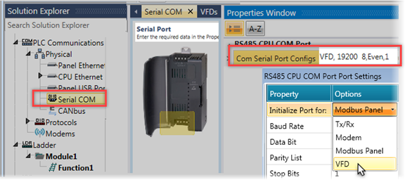
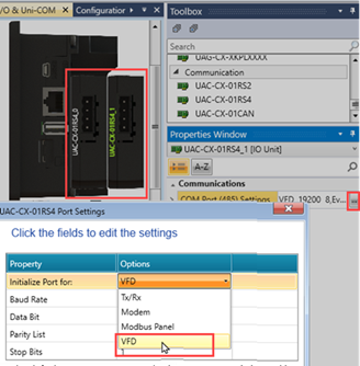
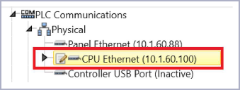
The VFD can only be connected to the serial port of the CPU, and may not be connected to a COM module.
In the Solution Explorer, select Hardware Configuration> PLC Communications > Physical, and select Serial Com.
In the Properties window, click to open the port options, and select VFD.
This will set the port to the default RS485 settings for RTU Modbus.
UniStream Built-in & UniStream PLC
You can add up to 2 RS485 Serial ports, configure them to VFD, and connect a VFD to each port.
|
|
|
Install the UMI-S0009 communication card according to the information in the B7 VFD installation manual, Appendix A Expansion cards.
|
|
In case of using the new UMI-S0009 multiprotocol card:
|
Using the VFD's display, set the card's Ethernet IP settings; the default Setting address, IP address, and subnet mask for each communication
card are 192.168.0.20, and 255.255.255.0 respectively.
VFD Parameter settings
P00.01=2 (communication as the running command channel)
P00.02=0 (Modbus TCP communication channel) to control VFD start and stop
P00.06=8 Modbus/Modbus TCP communication settings (Freq command channel)
P16.58= IP address Oct 1
P16.59= IP address Oct 2
P16.60= IP address Oct 3
P16.61= IP address Oct 4
P16.62= Subnet mask Oct 1
P16.63= Subnet mask Oct 2
P16.64= Subnet mask Oct 3
P16.65= Subnet mask Oct 4
P16.66= Default gateway Oct 1
P16.67= Default Gateway Oct 2
P16.68= Default Gateway Oct 3
P16.69= Default gateway Oct 4
P14.00= Local communication address 1-247
In UniLogic, set the CPU/IP address, using the same IP address family you set for the drive.
In the Solution Explorer>Hardware Configuration>Motion Drives>VFD, select UMI-U-B7.
Communication Type: select Ethernet, and under Communication Channel, set the VFD's address.
Modbus ID: enter the address you set in P14.00= Local communication address.

Under Hardware Configuration, Motion > VFDs; the list of available types opens in the Toolbox.
Double-click or drag your selected type into the Configuration window; UniLogic assigns a default name and a Modbus ID. UniLogic also creates a struct for that VFD.
Click the Communication channel field and select the RS485 port.
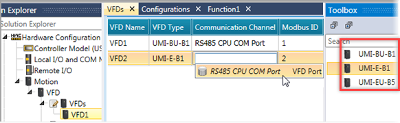
You can configure the VFD via its keypad, or via UniLogic.
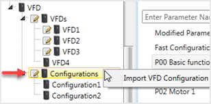
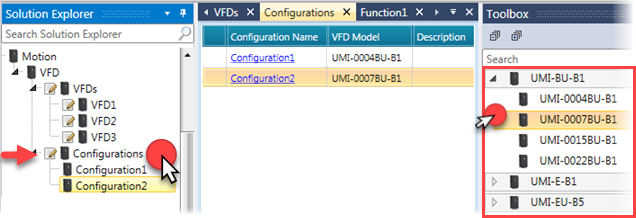
Under VFD, click Configurations to display the VFD types in the Toolbox.
Click the VFD type you require to display the list of available models and click to select your model; UniLogic automatically creates a Configuration.
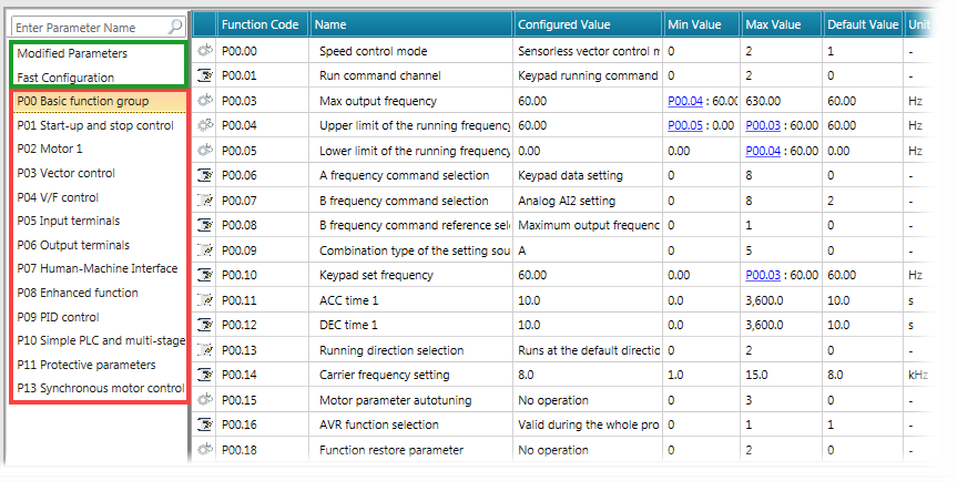
The image below shows a Configuration file, which you can edit by clicking in the parameter fields.
In the image, the right side shows groups of parameters. The groups outlined in green are specific to UniLogic:
Modified Parameters This contains any parameters which you have edited.
Fast Configuration This is a collection of the most frequently-used parameters.
The groups outlined in red are the standard parameter groups of the VFD model you are using.
|
|
After you edit the file via UniLogic, you can write the changes to the VFD in one of two ways.
Or
|
|
Additional Configuration Methods If you are connected to a VFD, right-click it in the Solution Explorer to upload its configuration file, edit it if required, and write it, via Ladder, into a VFD of that model. |
|
You can export, edit values, and import via Excel.
 You can only import a file that has been exported from UniLogic.
|
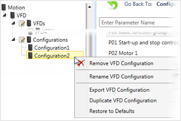
Right-click a specific Configuration
|
Right-click Configuration to import a file from Excel.
|
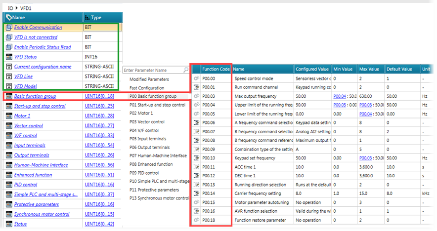
The VFD structs are located under I/Os.
UniLogic uses the VFD struct to contain the Configuration file parameter data, as shown in the next image.
The section of the struct outlined in green contains tags for parameters that are unique to UniLogic and UniStream; the rest of the struct contains tags that link to parameter groups in the VFD configuration file. For example, note the Basic Function Group outlined in red in the next image. The Configuration file contains 19 parameters; the linked UniLogic struct tag is an array of 18 UINT16.
|
Parameter Name |
Data Type |
Description |
|
Bit |
Turn this ON to allow communications between UniStream and the VFD. |
|
|
VFD is Connected |
Bit |
This is ON when the VFD is connected. |
|
When Enable Communication is turned ON, UniStream attempts to establish communications with the VFD and identify whether it is a Unitronics VFD.
Success: the VFD is identified as a Unitronics device. Both Enable Communication and VFD is Connected bits turn ON. Failure 1: the VFD is not a Unitronics device:
Failure 2: VFD Type mismatch (the VFD Type selected in UniLogic is not the actual VFD type that UniStream is attempting to communicate with:
|
||
|
Enable Periodic Status Read |
Bit |
|
|
Status |
UINT32 |
This must be reset by the user. -1= the VFD is not a Unitronics device -2 =VFD Type mismatch For all other Status codes, refer to the VFD Status codes in the manual. |
|
VFD Status |
INT 16 |
The exception response frame has two fields that differentiate it from a normal response frame: Exception Code Name Description |
|
Current Configuration Name |
String-ASCII |
The name assigned to the configuration. |
|
VFD Line (Type) |
String-ASCII |
The type of VFD selected in Hardware Configuration, for example |UMI-BU-B1 |
|
VFD Model |
String-ASCII |
The VFD model elected in Hardware Configuration,, for example UMI-0004BU-B1 |
|
Basic Function Group |
UINT16 (0-18) |
These relate to the parameter groups in the VFD Configuration. For details, refer to the manual for the specific VFD type. |
|
Start-
p and Stop Control |
UINT16 (0-25) |
|
|
Motor 1 |
UINT16 (0-28) |
|
|
Vector Control |
UINT16 (0-26) |
|
|
V/F control |
UINT16 (0-33) |
|
|
Input Terminals |
UINT16 (0-54) |
|
|
Output Terminals |
UINT16 (0-26) |
|
|
Human-Machine Interface |
UINT16 (0-56) |
|
|
Enhanced Function |
UINT16 (0-51) |
|
|
PID control |
UINT16 (0-16) |
|
|
Simple PLC and |
UINT16 (0-37) |
|
|
Protective parameters |
UINT16 (0-16) |
|
|
Synchronous motor control |
UINT16 (0-15) |
|
|
Status |
UINT16 (0-39) |
|
You can access the VFD via the VFD keypad, or via UniStream.
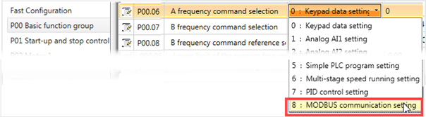
To enable UniStream to communicate with the VFD via the parameters in the VFD Configuration file, you must enable the VFD for Modbus communication.
In the P00 Basic Function group, set:
P00.01 to 2
P00.06 to 8.
In UniLogic, you can do this by manually editing the functions as shown below.

These functions may be considered as groups:
|
Group |
Function Name |
Purpose |
|
Configure the VFD |
VFD Read Configuration |
Reads (uploads) VFD Configuration file data from the VFD device to the VFD Struct |
|
VFD Write Configuration |
Writes all of the data in the VFD struct to the VFD device |
|
|
VFD Load Configuration from File |
Loads VFD Configuration data from the file specified in the function in UniLogic to the VFD struct |
|
|
VFD Store Configuration to File |
Stores the last loaded VFD Configuration of the VFD specified, to the Configuration file specified in the function |
|
|
Write Modified Parameters |
Writes only the VFD data that has been modified to the device and saves the successfully modified values to the struct |
|
Group |
Function Name |
Purpose |
|
Read / Write Parameters to the VFD |
VFD Read Parameter Direct |
Read a value from the VFD, directly from the specified parameter |
|
VFD Read Parameter InDirect |
Read a value from the VFD, indirectly, using a tag to store the parameter name (group and index) |
|
|
VFD Write Parameter Direct |
Write a value from the VFD, directly from the specified parameter |
|
|
VFD Write Parameter InDirect |
Write a value from the VFD, indirectly, using a tag to store the parameter name(group and index) |
|
Group |
Function Name |
Purpose |
|
Operate the VFD |
VFD Run Frequency Mode |
Use this to start running the VFD in Frequency Mode, at the frequency and direction specified in the ladder element. |
|
VFD Stop |
This stops the VFD, at the defined deceleration rate. |
|
|
VFD Jog Frequency |
Use this to start jogging the VFD, at the frequency and direction specified in the ladder element. |
|
|
VFD Stop Jogging |
Use this to stop jogging the VFD. |
|
|
VFD Run Torque Mode |
Starts the VFD in Torque Mode, at the torque and within the limits set in the function To run Torque Mode:
To enable torque limits to be set via keypad or enable the PLC to control torque, use P0.14 and P0.15 (6 = Modbus Control) |
|
|
VFD Emergency Stop |
Immediately stops the VFD (does not affect inertia) Note: The inverter cannot:
|
|
|
VFD Fault Reset |
Use this to reset the VFD Fault |
|
|
VFD AutoTune |
Use this to run Autotune on the VFD. |
VFD Ladder Function Status Codes
|
Code |
Message |
|
0 |
Success |
|
1 |
Pending (in Queue) |
|
2 |
In Progress |
|
-1 |
Enable Communication Bit is OFF (struct tag IO / InverterName / Enable Communication |
|
-2 |
Queue Full; retry after current program scan is complete |
|
-3 |
Enable Communication Bit has been turned OFF while pending requests are in queue (code 1), or requests are in progress (code 2) |
|
-4 |
Communication Timeout Exceeded |
|
-5 |
Configuration File Mismatch |
|
-6 |
Store/Load Configuration Error: File Name does not exist |
|
-7 |
VFD Write Modified Rebuild and download your project, if the error persists, contact Support |
|
The next two codes, -8 & -9 relate to Read/Write function commands that use indirect addressing. Commands are divided into 30 groups (P00-P29). A command is comprised of the group name, and a command parameter. For example, in the command P08.06, P08 refers to the 'Enhanced Functions' group, and 06 is the parameter 'Jog running ACC time'. |
|
|
-8 |
Read/Write, Group Number Error: the Group does not exist |
|
-9 |
Read/Write, Command Function Error: the parameter does not exist |
|
-10 |
Fault Message Response: these are communication errors. Check the code in struct tag IO / InverterName / Inverter Status, and refer to inverter manual, section Fault Message Response |
|
-11 |
Invalid Permission |
|
-12 |
Unexpected response from inverter |
|
-13 |
VFD identification in progress. Note that during the identification process, in the VFD struct, the VFD is Connected bit is OFF. |
|
-14 |
Auto-tune - Mode does not exist |
|
-15 |
RS485 Network data overload |
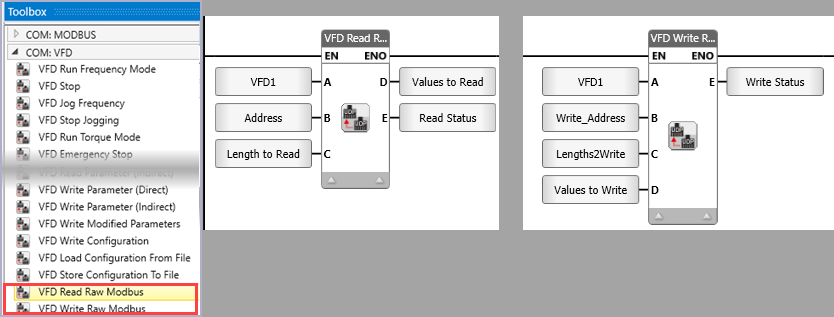
In addition to the functions listed above, you can use Ladder functions to read and write directly to a VFD via Modbus, using the addresses available in the VFD documentation.
Read/Write Direct Status Codes
|
Code |
Message |
|
0 |
Success |
|
1 |
Pending (in Queue) |
|
2 |
In Progress |
|
-1 |
Enable Communication Bit is OFF (struct tag IO / InverterName / Enable Communication |
|
-2 |
Queue Full; retry after current program scan is complete |
|
-3 |
Enable Communication Bit has been turned OFF while pending requests are in queue (code 1), or requests are in progress (code 2) |
|
-4 |
Communication Timeout Exceeded |
|
-5 |
Configuration File Mismatch |
|
-6 |
Store/Load Configuration Error: File Name does not exist |
|
-7 |
VFD Write Modified Rebuild and download your project, if the error persists, contact Support |
|
The next two codes, -8 & -9 relate to Read/Write function commands that use indirect addressing. Commands are divided into 30 groups (P00-P29). A command is comprised of the group name, and a command parameter. For example, in the command P08.06, P08 refers to the 'Enhanced Functions' group, and 06 is the parameter 'Jog running ACC time'. |
|
|
-8 |
Read/Write, Group Number Error: the Group does not exist |
|
-9 |
Read/Write, Command Function Error: the parameter does not exist |
|
-10 |
Fault Message Response: these are communication errors. Check the code in struct tag IO / InverterName / Inverter Status, and refer to inverter manual, section Fault Message Response |
|
-11 |
Invalid Permission |
|
-12 |
Unexpected response from inverter |
|
-13 |
VFD identification in progress. Note that during the identification process, in the VFD struct, the VFD is Connected bit is OFF. |
|
-14 |
Auto-tune - Mode does not exist |
|
-15 |
RS485 Network data overload |
|
-20 |
Reading/writing 0 or more than 16 registers at once |
|
-21 |
Number of registers to read/write is greater than size of provided array |
|
|
|