|
The UniStream PID algorithm is currently the same that is used by Vision series controllers. |
PID enables you to use system feedback to continuously control a dynamic process. The purpose of PID control is to keep a process running as close as possible to a desired Set Point. For more information, check the topic How PID Works.
PID Ladder Functions
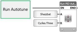
Run Autotune
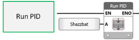
Run PID
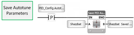
Save PID Autotune Data
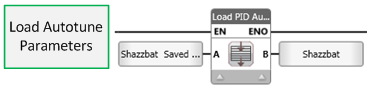
Load PID Autotune Data
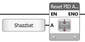
Reset PID Autotune
Force Error Integral
Pause Integral & Derivative Calculation
To implement PID, use the PID Ladder functions as explained in the next section.
![]() In order to ensure proper PID function, you should use the Run PID Autotune function. During the Autotune process, the function collects certain essential data. Unitronics' proprietary PID algorithm uses this data to run smooth, accurate PID loops.
In order to ensure proper PID function, you should use the Run PID Autotune function. During the Autotune process, the function collects certain essential data. Unitronics' proprietary PID algorithm uses this data to run smooth, accurate PID loops.
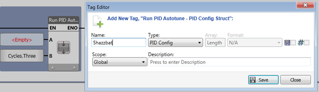
PID control is based on two structs: PID Config and PID AT Params.
The PID Config struct contains all of the parameters you need to configure, tune, and control PID.
A PID Config struct is created by UniLogic when you include a PID Ladder function in your program; you can also right-click in the Data Tag window to add one.
You use the PID AT Params struct to save the values from running autotune, load these values into the PID Config struct, and then run your PID loop.
|
|
|
You can either create a PID Config struct on the fly, PID Config struct on the fly, or link an existing one.
|
|
|
|
|
|
|
|
|
Note that before you begin, it is good practice to use the Reset PID Autotune to initialize the parameters in the PID Config struct. |
|
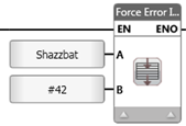
Force Error Integral function
Use this to to initialize or change the error value while the application is running. You can erase wind up error by writing '0' into the function, which is written into the PID loop's Integral Value in the PID Config struct.
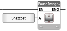
Pause Integral & Derivative Calculation
If conditions require, you can suspend these values and prevent them from changing. This may prove useful, for example, in a temperature application, when an opened oven door can cause a temporary temperature drop.
Note that the PID Status messages are located in the PID struct.
|
Name |
Data Type |
Definition |
|
Set Point (SP) |
INT32 |
The Set Point is the target value for the process. In a heating system, this is the temperature value set for the system. Note that the Set Point and Process value must be given in the same type of units (degrees Celsius, bars, meters per second, etc. |
|
Proportional Band (Kp) |
UINT16 |
Defines the proportional band, in units of 0.1%. The proportional band is a percentage of the total Process Value (PV). It is a range defined around the Set Point. When the PV is within this range, the PID function is active |
|
Integral Time (Ti) |
UINT16 |
Defines the integral time, in units of 1 second. Integral action responds to the rate of change in the controller’s CV output relative to the change in Error. The integral time you set is the amount of time, as calculated by the controller, required to bring the process to Set Point. |
|
Derivative Time (Td) |
UINT16 |
Defines the derivative time, in units of 1 second. Derivative action responds to the rate and direction of change in the Error. This means that a fast change in error causes a strong response from the controller. The derivative action ‘anticipates’ the PV’s value in relation to the Set Point and adjusts the CV accordingly, thus shortening the PID function’s response time. |
|
Sample Time (ST) |
UINT16 |
Defines the intervals between PID function updates, in units of 10mSecs. |
|
Input Low Limit (PV) |
INT32 |
Defines the lower limit for the Process Value. |
|
Input High Limit (PV) |
INT32 |
Defines the upper limit for the Process Value. |
|
Output Low Limit (CV) |
INT32 |
Defines the lower limit for the Control Value. |
|
Output High Limit (CV) |
INT32 |
Defines the upper limit for the Control Value. |
|
Reverse Action |
BIT |
Turn Off to activate Reverse Action (control type = heating), ON to activate Direct Action ( control type = cooling ). |
|
PID Mode |
UINT8 |
Reserved |
|
Control Value (CV) |
INT32 |
The Control Value is the output from the PID function. CV is output from the PID function and input to the process. Note that this output signal may be an analog or time-proportional variable value. |
|
Status |
INT16 |
Use these to implement ID and to check PID status. Value Message 0 status OK 4 PID running 5, 6 Setpoint change in progress 7 Integral-wind up 8Iintegral-wind down 9 Pause mode, Integral and Derivative values are not currently being calculated 10, 11 CV exceeds proportional band, no calculation performed 12, 13 AT parameter mismatch 14 Autotune complete Note that this means that PID will run without Auto-tune. The user may either rewrite the PID values to the 32-MI long Auto-tune vector, or may re-run Auto-tune -1 Proportion band zero. -2 Input range is invalid (PV input). -3 Output range is invalid (CV output). -4 Integral Overflow has reached maximum of 100,000. PID will not allow the Integral value to increase any further. -5 Auto-tune has not been performed. This status message is briefly displayed at the beginning of PID without Auto-tune -6 Set Point less then Input low range or Set Point more then Input high range. -7 to-10 Auto tune error. Auto-tune error. This status message is briefly displayed at the beginning of PID without Auto-tune -11 Noise is more than 5% of Input Range. -13 Autotune aborted. This may result if the Run Autotune element was not called for at least cycle during the autotune, or in the case of an unknown autotune error. |
|
Autotune Done |
BIT |
Turns ON when Autotune is complete. Reset by user. |
|
Control Value Proportional (CVp) |
INT32 |
Stores the Proportional Output. |
|
Control Value Integral (CVi) |
INT32 |
Stores the Integral Output. |
|
Control Value Derivative (CVd_ |
INT32 |
Stores the Derivative Output. |
|
Control Value Integral Error (CVie) |
INT32 |
Stores the Integral Error. |
|
Name |
Data Type |
Definition |
|
Set Point (SP) |
INT32 |
The Set Point is the target value for the process. In a heating system, this is the temperature value set for the system. Note that the Set Point and Process value must be given in the same type of units (degrees Celsius, bars, meters per second, etc. |
|
Proportional Band (Kp) |
UINT16 |
Defines the proportional band, in units of 0.1%. The proportional band is a percentage of the total Process Value (PV). It is a range defined around the Set Point. When the PV is within this range, the PID function is active |
|
Integral Time (Ti) |
UINT16 |
Defines the integral time, in units of 1 second. Integral action responds to the rate of change in the controller’s CV output relative to the change in Error. The integral time you set is the amount of time, as calculated by the controller, required to bring the process to Set Point. |
|
Derivative Time (Td) |
UINT16 |
Defines the derivative time, in units of 1 second. Derivative action responds to the rate and direction of change in the Error. This means that a fast change in error causes a strong response from the controller. The derivative action ‘anticipates’ the PV’s value in relation to the Set Point and adjusts the CV accordingly, thus shortening the PID function’s response time. |
|
Sample Time (ST) |
UINT16 |
Defines the intervals between PID function updates, in units of 10mSecs. |
|
Input Low Limit (PV) |
INT32 |
Defines the lower limit for the Process Value. |
|
Input High Limit (PV) |
INT32 |
Defines the upper limit for the Process Value. |
|
Output Low Limit (CV) |
INT32 |
Defines the lower limit for the Control Value. |
|
Output High Limit (CV) |
INT32 |
Defines the upper limit for the Control Value. |
|
Reverse Action |
BIT |
Turn Off to activate Reverse Action (control type = heating), ON to activate Direct Action ( control type = cooling ). |
|
PID Mode |
UINT8 |
Reserved for future implementation |
|
Data |
Buffer |
Internal Use Only |