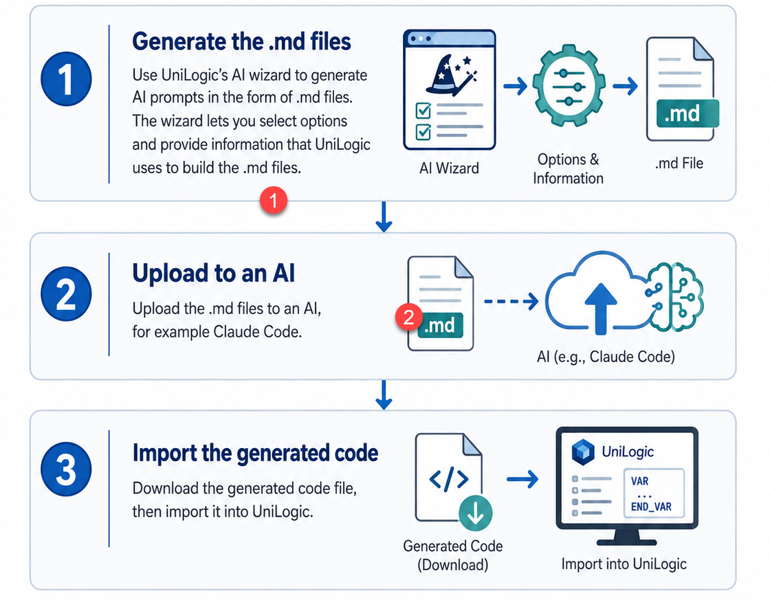
UniLogic's AI feature helps you generate Structured Text applications without writing prompt text yourself. The built-in AI Prompt Generator wizard collects your application requirements through a structured form, then produces two Markdown (.md) files that carry everything the AI needs to generate your code.
This topic walks you through the complete workflow from opening the wizard to importing the generated code into your UniLogic project.
The example in this topic is based on a Water and Wastewater application, and assumes you are using Claude AI code assistant.
The Generate / Modify / Other selector field on the first wizard page determines what the AI will produce. Choose the option that matches your goal before filling in the rest of the wizard.
|
Option |
What it generates |
Required input |
Typical output |
|
Generate Application |
A full PLC application structure |
Project purpose, I/O, modes, alarms, HMI tags, control sequences |
Multiple functions, tag lists, and complete control logic |
|
Generate Function |
One specific ST function |
Function purpose, inputs, outputs, local variables, logic rules |
A single, ready-to-import ST function |
|
Modify Function |
A revised version of existing code |
Your existing ST code plus a precise description of the required change |
Revised ST function with the change applied |
|
Generate Comments |
Commented version of existing code |
Your existing ST code plus preferred comment style |
The same code with explanatory comments added throughout |
|
Code Review |
An analysis report (not code) |
Your existing ST code plus the review checklist |
Findings, risk flags, and improvement suggestions |
|
Code Porting |
UniLogic-compatible ST equivalent |
Source code from another PLC platform plus target requirements |
ST code structured for UniLogic import |
|
Image-generation instructions for a UniLogic HMI widget |
Widget type, image definition, and styling choices |
A single Markdown (.md) prompt file for the AI image engine |
The following example shows you how to generate a control application in Structured Text.
Open the wizard by clicking AI on the UniLogic toolbar, then clicking Prompt Generator. The wizard guides you through four numbered steps: Project Identity, Functional Description, Additional Info, and Generate.
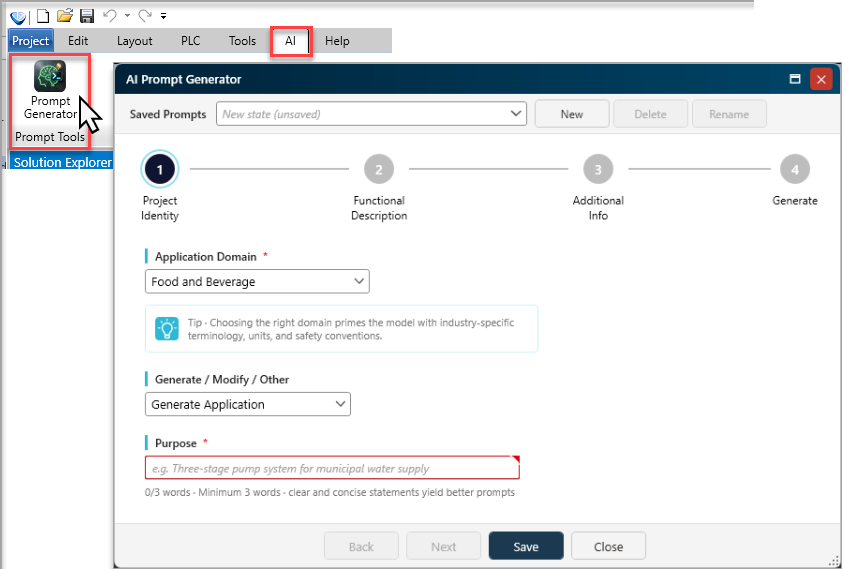
Fill in the fields on this page, then click Next to proceed to Functional Description.
|
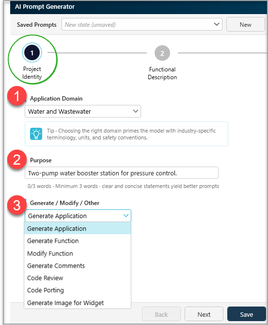
Application Domain |
Select the industry that best matches your project from the drop-down list. Choosing the correct domain primes the AI with the right terminology, units, and safety conventions. |
|
Purpose |
Enter a short, specific statement describing what the application does. Aim for at least three words.
|
|
Generate / Modify / Other |
Select the action you need the AI to perform. Your selection determines which fields appear on the next page. Generate Application: You want the AI to generate a complete application or application-level logic. Generate Function: You want the AI to generate a specific ST function. Modify Function: You want the AI to modify an existing ST function. Generate Comments: You want the AI to add or generate comments for existing code. Code Review: You want the AI to review code and provide feedback. Code Porting: You want the AI to help adapt or port existing code. Generate Image for Widget: You want the AI to generate a prompt for an industrial SVG image for an HMI widget. Selecting this option opens a four-step image wizard. |
This page captures the substance of your application.
Fill in the fields, make your selections, and then click Next to proceed to Additional Info.
|
|
|
|
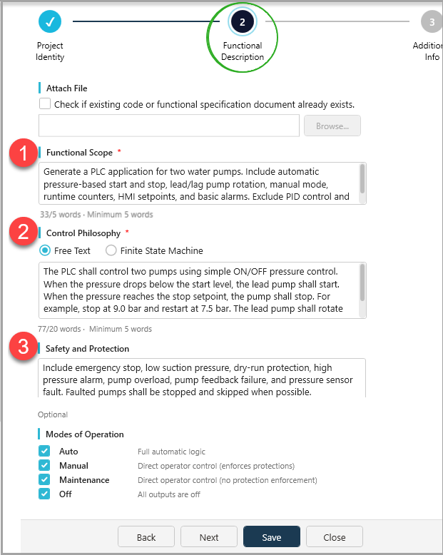
Attach File (optional) |
If you have an existing ST function you want to modify or comment, or a detailed functional specification document, tick the checkbox and browse to the file. The file is embedded in the generated Prompt.md. |
|
Functional Scope |
Describe what the application must do and what it must not do. Be explicit about both. Minimum 5 words. |
|
Control Philosophy |
Choose between Free Text (describe the logic in your own words) and Finite State Machine (list states and transitions). Select whichever is more natural for your application. The minimum Free Text entry is 5 words. The more detail you provide here, the more accurate the generated code will be. |
|
Safety and Protection |
List every safety function, interlock, and protection that must be included. The AI will not assume protections that are not listed |
|
Modes of Operation: Optional |
Auto: Full automatic logic Manual: Direct operator control (enforces protections) Maintenance: Direct operator control (no protection enforcement) Off: All outputs are off |
|
|
You can skip this screen entirely. Tag selection is not required — the AI generates a complete, self-contained tag set from your Functional Description alone. |
The information on this screen is optional. It lets you select existing tags from your UniLogic project, so that the generated code uses your actual tag names instead of creating new ones.
Fill in the fields and make your selections if desired, and then click Next to proceed to Generate.
 |
To include user defined tags, they must comply with the ST standard. The standard requires variable identifiers to match the following rule: the name must start with a letter or underscore, and may only contain letters (A–Z, a–z), digits (0–9), and underscores." In addition, note that digits cannot be the first character. |
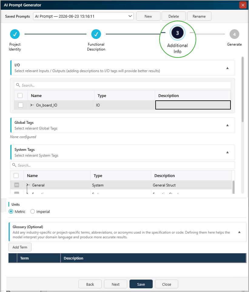
The following categories are available for Additional Info:
|
I/O |
Shows available input/output structures. Selecting relevant I/O can help the AI reference existing hardware-related tags. |
|
Global Tags |
Tags already declared in your project's Global Variable List. |
|
System Tags |
Unitronics system-defined structs such as System_Data, Panel Events, and hardware module data |
|
User-defined |
You can also select user-defined structs and relevant enums |
|
Units |
You can switch between Metric and Imperial. |
|
Glossary |
Here, you can add glossary entries--abbreviations, acronyms, or project-specific expressions—and their meaning. |
The Generate page shows a Prompt Summary so you can verify your entries before proceeding. Check that the Domain, Purpose, Generate action, and other details are correct.
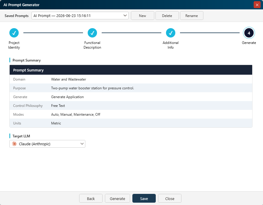
Select your Target LLM from the drop-down list. Choose Claude (Anthropic) to use the Claude AI assistant.
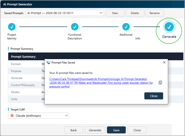
Click Generate. UniLogic creates a folder in your Downloads directory and saves two .md files inside it:
Prompt.md: Everything you entered in the wizard: domain, purpose, functional scope, control philosophy, safety requirements, and any tags you selected.
Unitronics_UniStream_ST_Program_Generation_Instructions.md: Detailed UniStream / UniLogic ST coding rules and constraints that the AI must follow when generating code.
UniLogic creates the target folder automatically; you can click the hyperlink shown in the wizard to navigate to the folder.
Open the assistant and start a new chat.
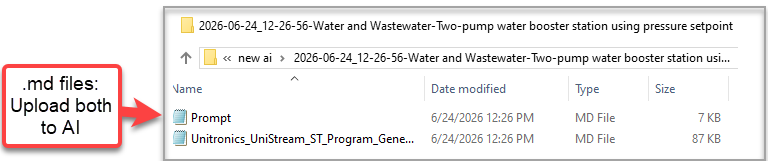
Click the Add files icon in the AI message input area, then select both .md files at once from the folder UniLogic generated:
Prompt.md
Unitronics_UniStream_ST_Program_Generation_Instructions.md
Upload both .md files
|
Upload both Markdown files in the same AI message. Do not upload only Prompt.md. The Instructions file contains UniLogic ST generation rules and constraints that the AI needs in order to format the code correctly. |
After attaching both files, click Send (or press Enter) without typing anything in the message box. All the instructions the AI assistant needs are already inside the .md files.
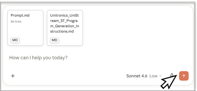
The assistant reads both files, confirms it understands the project requirements, and then generates the ST application. For a full application this typically takes one to two minutes.
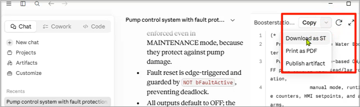
When the assistant finishes, the generated code appears in an artifact panel. Download and save it as an .st file.
|
|
Name the file something descriptive before saving, for example BoosterStation_UniLogic.st. This makes it easier to locate when importing into UniLogic. |
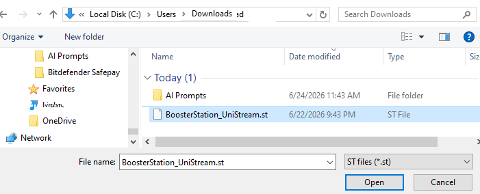
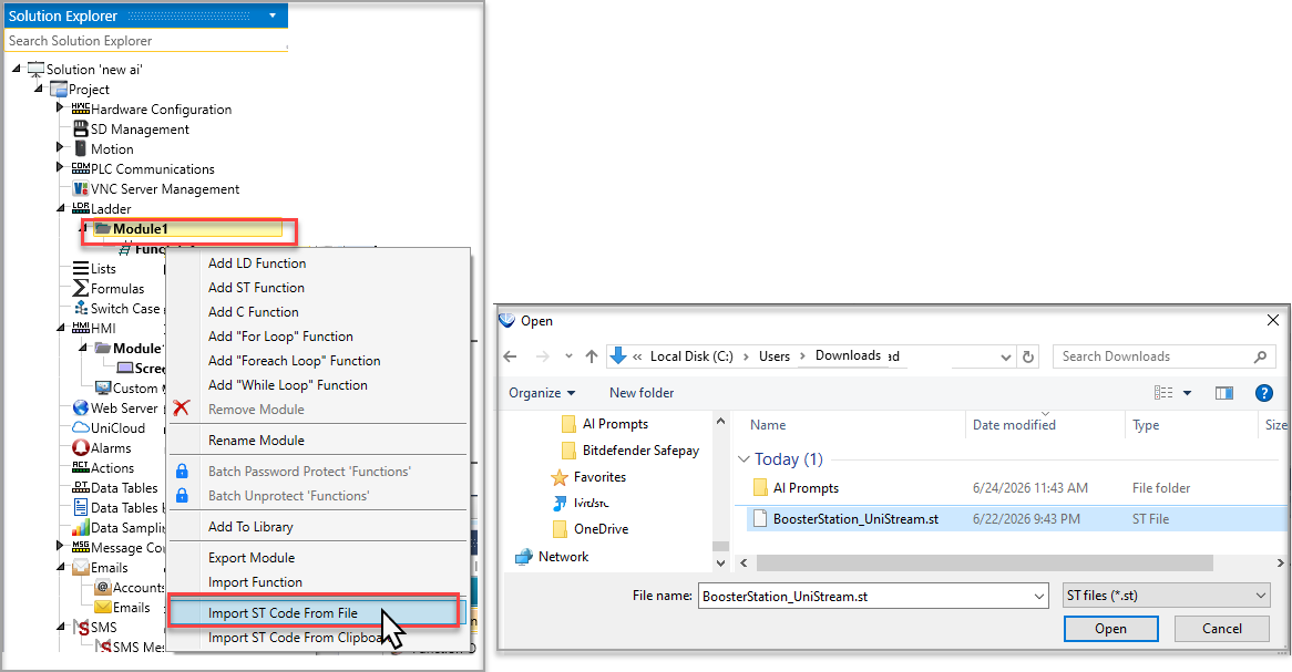
In the UniLogic Solution Explorer, right-click the Ladder module where you want to add the generated code, then click Import ST Code From File. Browse to and select the .st file you downloaded from Claude.
|
|
Import time depends on the size of the generated application. A full multi-function application with dozens of tags typically imports in a few seconds. |
UniLogic processes the entire file and creates:
All ST functions (listed in the Solution Explorer under the Ladder module)
All global tags (visible in the Global tag table)
All struct types (visible in the STRUCTS pane)
All enum types (visible in the ENUMS pane)
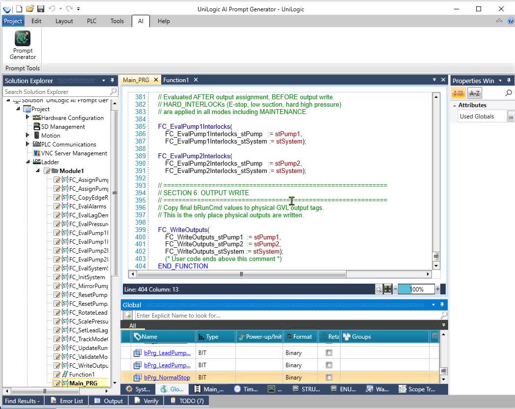
The generated code is a solid starting point, not a finished application. Before deploying to hardware, complete the following steps:
Link I/O tags to hardware channels
The generated GVL declares all I/O tags by name and type only. Physical channel binding is not included in the ST code. For each input and output tag, open the Hardware Configuration in UniLogic and link the tag to its physical I/O channel.
Review and calibrate setpoints
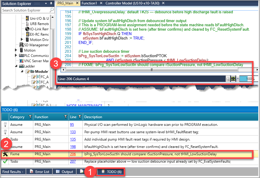
Search the imported code for FIXME comments. These mark every value that was assumed during generation and requires calibration against your actual site conditions — for example, pressure thresholds, timer durations, and scaling factors. Replace all FIXME values with confirmed site data before testing.
Review ASSUME comments
Search for ASSUME comments. These explain every assumption the AI made about your process that was not explicitly stated in the wizard. Verify each assumption against your actual application requirements.
Check the TODO panel
UniLogic prepares a list of outstanding issues for you to review in the TODO tab at the bottom.
Compile and correct errors
Build the project in UniLogic. Resolve any compilation errors — most commonly caused by tag name conflicts or missing I/O assignments. The Error List panel shows the location and description of each error.
Test on hardware
Commission and test the application on your target hardware before placing it into service. The generated code enforces safety interlocks as described in your wizard input, but all safety-critical logic must be verified independently against your application's actual safety requirements.
Be specific about what to exclude as well as what to include in the Functional Scope field. This prevents the AI from generating unnecessary logic.
Use the Finite State Machine option in Control Philosophy if your process has clearly defined operating states. The resulting code will be more structured and easier to follow.
List every safety protection explicitly. The AI does not infer protections from context — if it is not in the wizard, it will not appear in the code.
Save your completed wizard entries using the Save button on any wizard page. Saved prompts appear in the Saved Prompts drop-down so you can reuse or refine them later.
If the generated application is larger than expected, you can ask Claude to explain any section of the code by following up in the same chat. The Instructions file is already loaded.
|
Issue |
Possible cause |
Action |
|
AI generates generic or incomplete code |
Only Prompt.md was uploaded |
Upload both Markdown files in the same message. |
|
Code does not import |
File was not saved as .st, or content was copied incorrectly |
Download the artifact as an .st file or verify the file extension. |
|
Compile errors occur after import |
Tag conflicts, missing I/O assignments, or assumptions requiring review |
Check Error List, TODO panel, FIXME, and ASSUME comments. |
|
Generated logic is larger than expected |
Functional Scope included broad or ambiguous requirements |
Refine the saved prompt and specify exclusions. |
|
Safety logic is missing |
Protection was not listed explicitly |
Add the protection to Safety and Protection and regenerate. |
This is the text that was used for the example in this topic.
You can use it to walk through generating your first ST project using the UniLogic AI feature. Simply copy and paste the text into the appropriate field, generate your .md files, upload to your AI assistant, generate your ST application and import to UniLogic--exactly as shown in this topic.
Purpose
Two-pump water booster station using pressure setpoint ON/OFF control.
Functional Scope
Generate PLC logic for a two-pump water booster station. Include automatic start and stop based on discharge pressure setpoint with configurable hysteresis, lead/lag pump rotation, manual and automatic operating modes, pump availability checks, runtime monitoring, HMI setpoints, alarm handling, and basic SCADA monitoring tags. Exclude PID control, VFD speed control, chemical dosing, filtration control, and remote SCADA write-back commands.
Control Philosophy — Finite State Machine Option
Idle → System Ready → Start Lead Pump → Single Pump Running → Start Lag Pump → Two Pumps Running → Stop Pumps → Fault Handling
State descriptions:
Idle: System disabled or pressure is above the start threshold. Pumps are stopped.
System Ready: PLC checks system enable, pressure sensor status, emergency stop, low suction pressure, and pump availability.
Start Lead Pump: The selected lead pump starts when pressure is below the start threshold.
Single Pump Running: One pump runs until pressure reaches the stop threshold. If pressure remains low for too long, the system requests the second pump.
Start Lag Pump: The second available pump starts after a configurable delay if one pump cannot restore pressure.
Two Pumps Running: Both pumps run until pressure reaches the stop threshold.
Stop Pumps: Pumps stop when pressure reaches the stop threshold, for example 9.0 bar.
Fault Handling: Faulted pumps are stopped, alarms are raised, and the system continues with the healthy pump if possible.
Safety and Protection
Include low suction pressure protection, dry-run protection, high discharge pressure trip, pump overload fault, motor thermal fault, pump feedback failure, pressure transmitter failure, emergency stop, and configurable start/stop delays. Critical system faults shall stop both pumps and require operator reset after the fault is cleared. Individual pump faults shall stop only the affected pump and allow operation with the remaining healthy pump when possible.
 Short, concrete purpose statements consistently produce better results than long or vague ones. Focus on the core function, not the context.