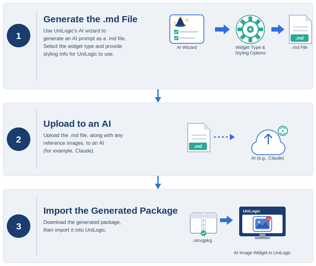
UniLogic's AI feature helps you generate SVG images for HMI widgets without writing prompt text yourself. The built-in AI Prompt Generator wizard collects your application requirements through a structured form, then produces a Markdown (.md) file that carries everything the AI needs to generate your image.
This topic walks you through the complete workflow from opening the wizard to importing the generated file into your UniLogic project.
The following example shows you how to generate an industrial SVG image used in the HMI.
Open the wizard by clicking AI on the UniLogic toolbar, then clicking Prompt Generator. The wizard guides you through four numbered steps: Project Identity, Image Definition, Styling, and Review & Export.
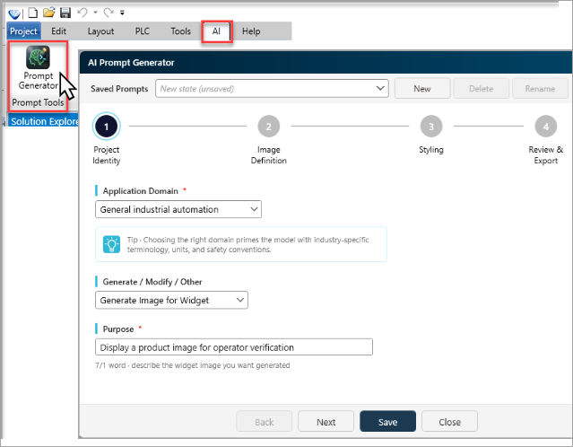
Fill in the fields on this page, then click Next to proceed to Image Definition.
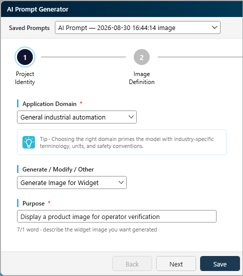
|
Application Domain |
Select the industry that best matches your project from the drop-down list. Choosing the correct domain primes the AI with the right terminology, units, and safety conventions. |
|
Generate / Modify / Other |
Select the action you need the AI to perform. Your selection determines which fields appear on the next page. Generate Image for Widget: You want the AI to generate a prompt for an industrial SVG image for an HMI widget. Selecting this option opens a four-step image wizard. |
|
Purpose |
Enter a short, specific statement describing the widget image you want generated. Aim for at least one word.
|
Fill in the fields, make your selections, and then click Next to proceed to Styling.
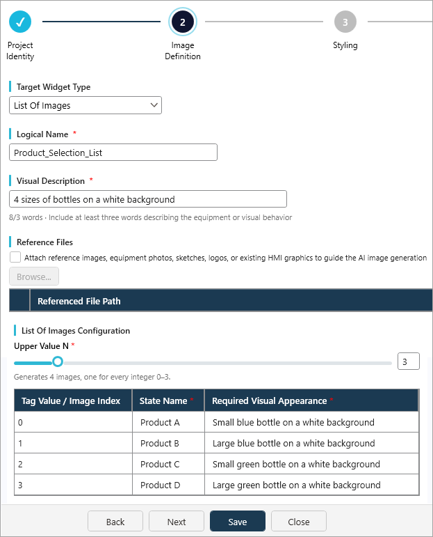
|
Target Widget Type |
Select the widget type from the drop-down list. Your selection determines which additional fields appear in the Configuration section below. |
|
Logical Name |
A short identifying name for the widget. This name is used to build the exported file name. |
|
Visual Description |
Describe the equipment, orientation, physical details, and any required visual behavior. A minimum of three words is required. |
|
Reference Files (Optional) |
If you have reference images, equipment photos, sketches, logos, or existing HMI graphics to guide the AI image generation, tick the checkbox and browse to the file. |
|
Image Configuration |
Image: No value-state mapping is required List Of Images: Enter the List Upper Value (N). Range Of Images: Enter Minimum, Maximum, and Unit for the full engineering range, plus the Number Of Images to generate. Binary Image: The linked UniLogic Boolean value selects one of two images. |
The information on this screen is optional. Fill in the fields and make your selections if desired, and then click Next to proceed to Review & Export.
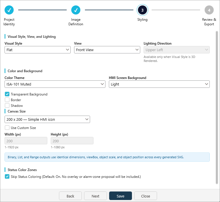
|
Visual Style, View, and Lighting |
Visual Style: Flat (default), Modern Flat, Line Art, Geometric, or 3D Rendered View: Front View, Isometric View, or Camera View Lighting Direction: Upper Left, Upper Right, or Overhead. Enabled only when Visual Style is 3D Rendered |
|
Color and Background |
Color Theme: ISA-101 Muted (default) or Colorful + Gradient HMI Screen Background: Light (default) or Dark - the HMI screen background the icon will be viewed against. This is independent of Transparent Background below Transparent Background, Border, Shadow: Checkboxes. Transparent Background is on by default; Border and Shadow are off by default |
|
SVG Drop-Shadow Filter |
Applies only when Visual Style is 3D Rendered and Shadow is on |
|
Canvas Size |
Choose a preset from the drop-down list (for example 200x200 - Simple HMI icon), Binary, List, and Range outputs use identical dimensions, viewBox, object scale, and object position across every generated SVG. |
|
Status Color Zones |
Optional status-state coloring. For List Of Images and Range Of Images, a Skip Status Coloring option controls whether a zone table (Start / End / Color) is shown. Status Color Zones are unrelated to the UniLogic Alarm widget. |
|
|
Unitronics assumes no responsibility for AI-generated results. Always verify and validate all outputs before use. |
Review the summary of your entries, grouped under Project and Image, Visual Parameters, Image Configuration, and Status Coloring.
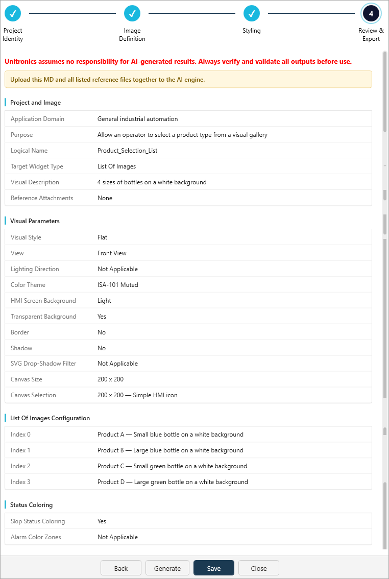
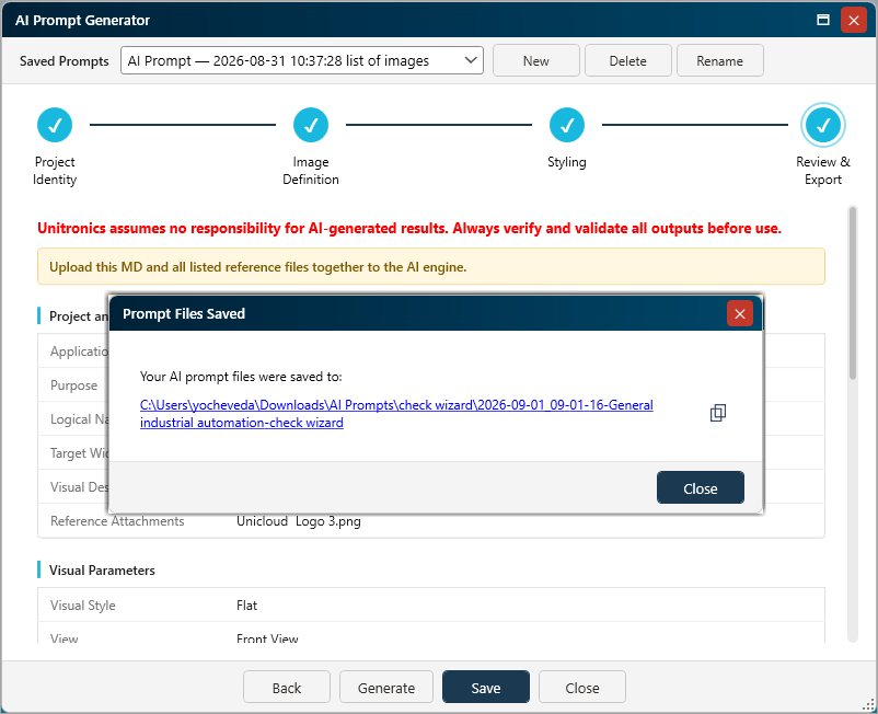
Click Generate. UniLogic creates a folder in your Downloads directory and saves a single downloadable Markdown (.md) file inside it. The file is named from your Logical Name - for example, a Logical Name of "Product_Selection_List" produces product_selection_list_AI_SVG_Image_Generation_Prompt.md
UniLogic creates the target folder automatically; you can click the hyperlink shown in the wizard to navigate to the folder.
Open the assistant and start a new chat.
Click the Add files icon in the AI message input area, then select the .md file and all listed reference files (if applicable), at once from the folder UniLogic generated:
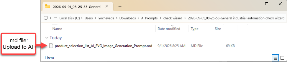
After attaching the file, click Send (or press Enter) without typing anything in the message box. All the instructions the AI assistant needs are already inside the .md file.
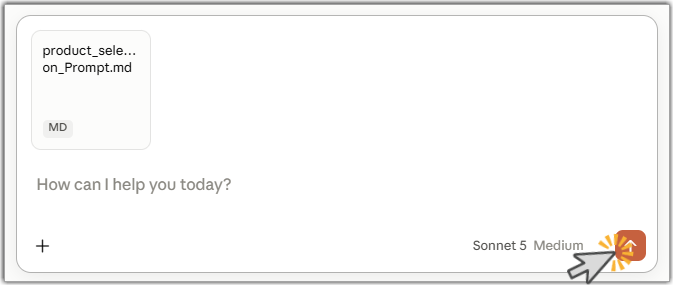
The assistant reads the file, confirms it understands the project requirements, and then presents three concept preview to choose from (or lets you skip this step) before generating the final deliverable. This typically takes one to two minutes.
When the assistant finishes, the AI generates a ZIP archive containing one SVG file per required state, a manifest.json file, and an optional preview.png rendering.
The number of SVG files depends on the Target Widget Type:
1 for Image
2 for Binary Image
N + 1 for List Of Images
The specified Number Of Images for Range Of Images
Download and save it as an .uisvgpkg file.
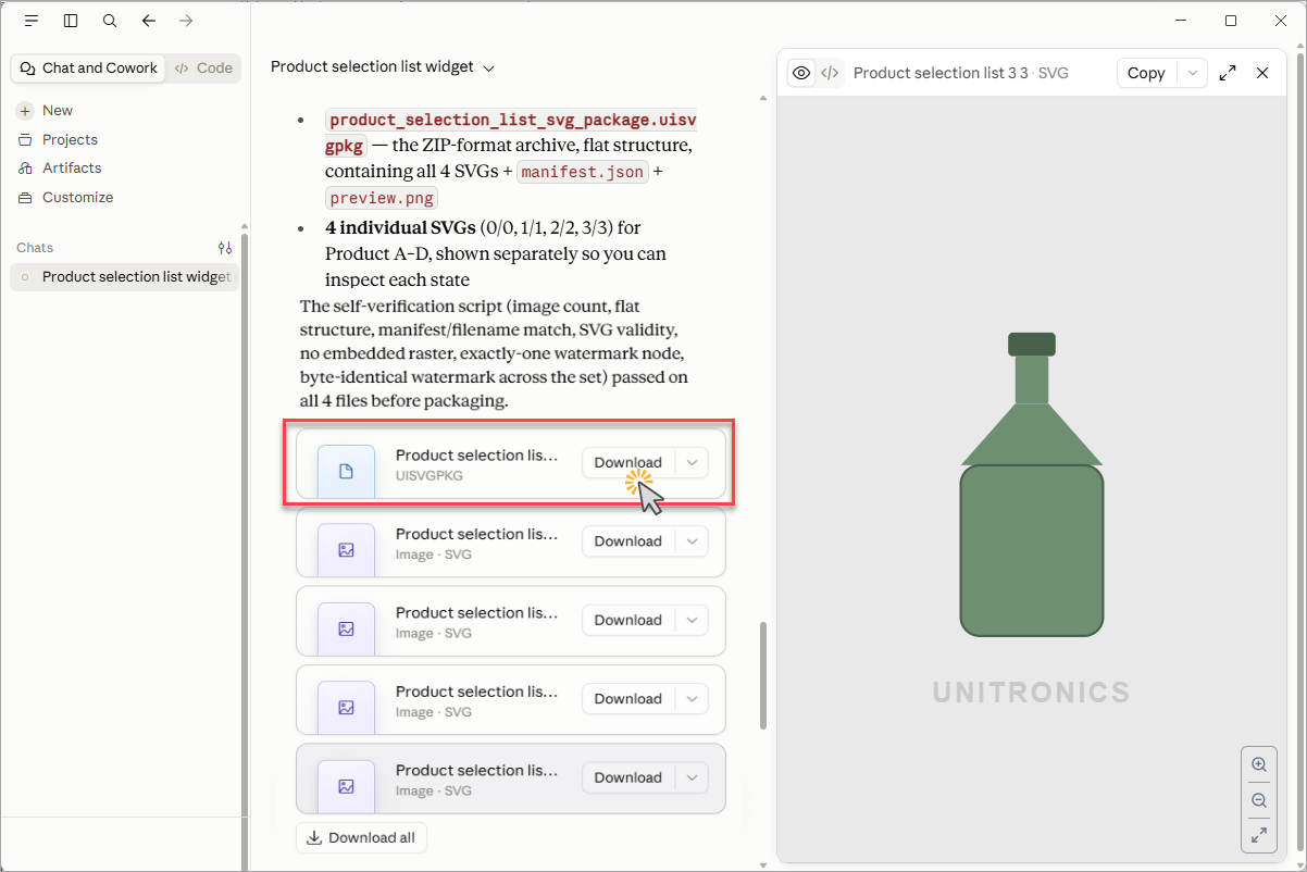
|
|
Name the file something descriptive before saving, for example Classic_Tapered_Bottle_List_UniLogic.uisvgpkg. This makes it easier to locate when importing into UniLogic. |
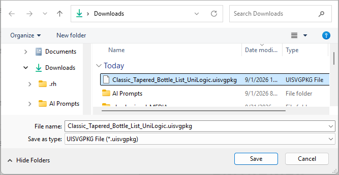
Via Properties Window
In UniLogic navigate to HMI > Image Elements > AI Image Widget.
Insert the element either:
- Press Enter or double-click it to place it on the screen
or
- Use your mouse to drag-and-drop the element to the desired location.
Click Import Package, browse to and select the .uisvgpkg package you downloaded from Claude.
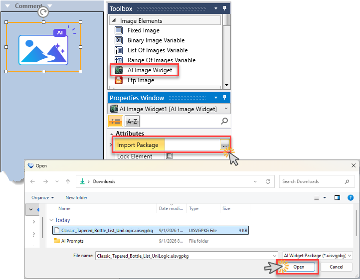
Via File Explorer
Browse to the .uisvgpkg package you downloaded from Claude, and drag-and-drop it on the HMI display.
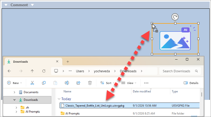
UniLogic processes and imports the entire package.
The imported package populates the AI Image Widget with the generated SVG asset(s), replacing the placeholder icon.
See HE: AI Image Widget for how the widget behaves after import and how to configure it.
Related topics
 Short, concrete purpose statements consistently produce better results than long or vague ones. Focus on the core function, not the context.