![]()
If a Data Table is marked as Part of Project, you cannot copy it or log lines from it to an SD card.
These functions enable you to:
Log a single row of data from a Data Table into a .ulg file located on the SD card
Write all or part of a Data Table into a .udt file located on the SD card
Read all or part of an SD card .udt file to a Data Table
Search for tagged sections in a .udt file
|
|
If a Data Table is marked as Part of Project, you cannot copy it or log lines from it to an SD card. |
|
# |
Description |
Value |
Comments |
|
SI 64 |
Maximum number of DT files that can be saved (read-only) |
0-64 The maximum amount of Trend files (*.udt files) in a single folder is 64. The value in SI 634shows the number of remaining *.udt files; if 5 *udt files exist, SI 64 = 59 |
|
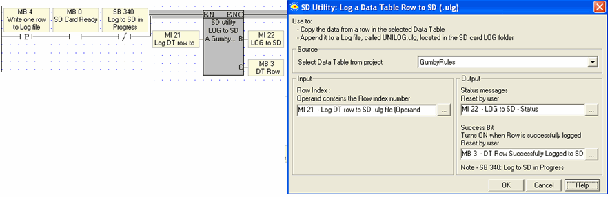
To log a row from a Data Table, build a net that includes the function SD> Write Log Line to SD.
Use SB 340 to ensure that the PLC is not currently logging a row to the SD card.
When the application writes this type of data to the SD card, it creates a single file called UNILOG.ulg in the LOG folder, and then appends each new line from the selected Data Table to this log file.
|
Parameter Name |
Purpose |
|
Source |
Selects the Data Table you want to log from. |
|
Row index |
Determines which row in the table will be logged. |
|
Status messages |
This MI is a bitmap; a bit turns ON to indicate status. The MI is initialized when the function starts.
All bits OFF – No errors, and the SD card is idle Bit 1 – The SD card was formatted in an SD Tools version that is not compatible with the VisiLogic application in the PLC. or VisiLogic version is not compatible with the PLC OS. Check to see if you need to update versions. Bit 2 – The data in the SD is not compatible with the data in the Data Table Bit 3 – Data checksum error Bit 4 – Failed to open file Bit 5 - Failed to write to the SD file Bit 6 - Failed to close file Bit 7 - In progress Bit 8 - No SD card found Bit 9 - SD error, check SI 66 for error message Bit 10 – Requested Data Table does not exist |
|
Success Bit |
Turns ON when the data is successfully written to the SD card. It remains ON until it is reset by the application, or until the application calls the function. |
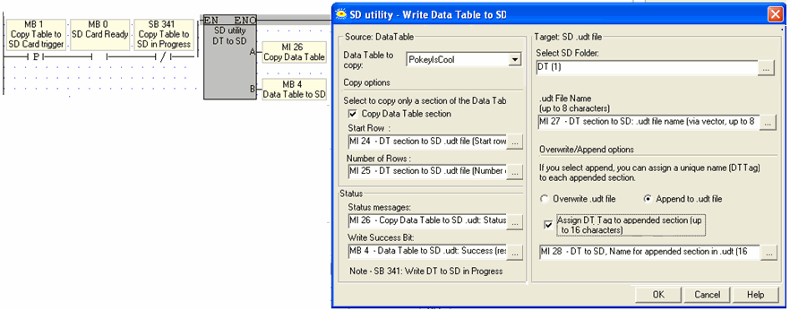
The Ladder function DT to SD creates .udt files and saves them in the main DT folder or in one of four sub-folders. DT1, DT2, DT3, DT4.
Each folder can contain 64 files, for a total of 320 .udt files.
Write Data Table to SD (Copy DT to SD)
To copy an entire or partial Data Table, build a net that includes the function SD> Write DataTable to SD.
Use an inverted contact of SB 341 to ensure that the PLC is not currently writing to the SD card.
Set the options to copy all or part of a Data Table.
When the application writes this type of data to the SD card, it creates a file with the extension .udt in the selected DT folder.
|
Parameter Name |
Purpose |
|
Source: |
Selects the Data Table you want to write from. |
|
Copy options |
Select to copy all or part of a Data Table. Selecting Copy enables the Start Row and Number of Rows parameters. |
|
Target: SD Folder |
This is where the .udt file will be stored on the SD card. You can select the folder, or provide the Folder number via register. Values point to folders as follows: 1=the main DT folder, 100=DT1, 101=DT2, 102=DT3, and 103=DT4. |
|
.udt File Name |
Can be up to 8 characters long, and may be provided by constant text or register. Note that if the name comes from an MI, the function copies a vector 8 bytes long, or until it finds a 'null' character. |
|
Overwrite/Append |
If the function finds a .udt file in that folder of the same name,
|
|
Status messages |
This MI is a bitmap; a bit turns ON to indicate status. The MI is initialized when the function starts.
All bits OFF – No errors, and the SD card is idle Bit 1 – The SD card was formatted in an SD Tools version that is not compatible with the VisiLogic application in the PLC. or VisiLogic version is not compatible with the PLC OS. Check to see if you need to update versions. Bit 2 – The structure of the .udt file and the Data Table are not identical Bit 3 – Data checksum error. Please send application and any related information to [email protected]. Bit 4 – Failed to open file Bit 5 - Failed to read from file Bit 6 - Failed to close file Bit 7 - In progress Bit 8 - No SD card found Bit 9 - SD error, check SI 66 for error message Bit 10 – Requested Data Table does not exist |
|
Success Bit |
Turns ON when the data is successfully written to the SD Card. It remains ON until it is reset by the application, or until the application calls the function. |
|
Note ♦ |
The maximum number of Data Table files that can be created in a folder SD card is 64, including the main DT folder. |
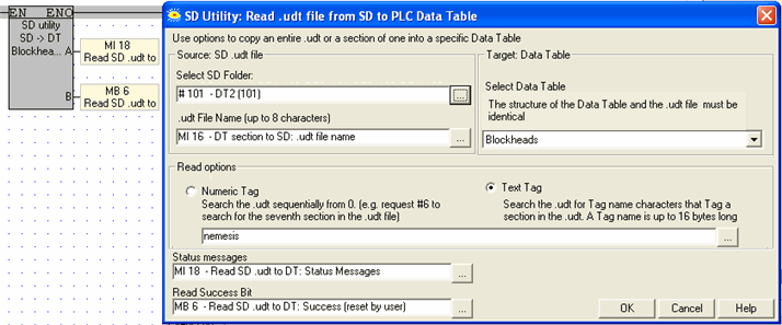
Read .udt file from SD to PLC Data Table (Copy SD >DT)
To copy .udt data from an SD card into a Data Table, build a net that includes the function SD> Copy Data to PLC Data Table.
Use an inverted contact of SB 342 to ensure that the PLC is not reading writing from the SD card.
Note that in order to copy data, the Data Table structure in both PLC and SD card must be identical: equal number of rows, equal numbers of columns, and column data types.
|
Parameter Name |
Purpose |
|
Select SD Folder |
This is where the source .udt file is on the SD Card. You can select the folder, or provide the Folder number via register. Values point to folders as follows: 1=the main DT folder, 100=DT1, 101=DT2, 102=DT3, and 103=DT4. |
|
File Name |
The Table Name can be up to 8 characters long, and may be provided by constant text or register. |
|
Read Options |
If the .udt file contains appended sections, you can search for a Numeric or Text Tag. |
|
Target: Data Table
|
Click on the drop-down arrow to select a Data Table in the project. The Table Name can be up to 8 characters long, and may be provided by constant text or register. Note that if the name comes from an MI, the function copies a vector 8 bytes long, or until it finds a 'null' character. |
|
Status Operand |
This MI is a bitmap; a bit turns ON to indicate status. The MI is initialized when the function starts.
|
|
Success Bit |
Turns ON when the data is successfully read. It remains ON until it is reset by the application, or until the application calls the function. |
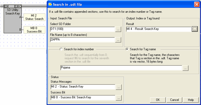
If a .udt file was created using appended sections, you can search it for the index number or tag name.
Use an inverted contact of SB 342 to ensure that the PLC is not reading writing from the SD card.
|
Parameter Name |
Purpose |
|
Select SD Folder |
This is where the source .udt file is on the SD Card. You can select the folder, or provide the Folder number via register. Values point to folders as follows: 1=the main DT folder, 100=DT1, 101=DT2, 102=DT3, and 103=DT4. |
|
File Name |
The Table Name can be up to 8 characters long, and may be provided by constant text or register. |
|
Tag Type |
Search for a Numeric or Text Tag. |
|
Table
|
Click on the drop-down arrow to select a Data Table in the project. The Table Name can be up to 8 characters long, and may be provided by constant text or register. Note that if the name comes from an MI, the function copies a vector 8 bytes long, or until it finds a 'null' character. |
|
Status Operand |
This MI is a bitmap; a bit turns ON to indicate status. The MI is initialized when the function starts.
|
|
Success Bit |
Turns ON when the tag is found. It remains ON until it is reset by the application, or until the application calls the function. |