Read enables you to copy values from a Data Table to PLC operands.
Write functions enables you to copy operand values from a PLC to Data Tables.
Read/Write functions are located on the Data Tables menu.
Note ♦ |
The maximum number of operands of any type for a Read/Write operation is 128. |
♦ |
After performing a Read Timer operation, reset the timer that has been read. |
Use the Read function to select Data Table rows and read their data into PLC memory operands. Values are read from the Data Table into the operands that are linked to it in the Read function. Note that the number of rows read cannot exceed the number of rows that are in the Data Table.
Use the Write function to select PLC memory operands and read their data into Data Table rows.
Values are read from the PLC into the Data Table cells that are linked to it in the Write function.
Note that you provide a Start Address for the PLC memory operands; the Write function will take a vector of operands that will fit the number of rows in the Data Table.
Note ♦ |
'Part of Project' Data cannot be included in Write Column functions. |
♦ |
Not all Data Types are supported:
|
♦ |
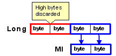
When longer data types are copied to shorter data types, the longer values are truncated. |
♦ |
When shorter data types are copied to longer types, each source value is copied to the lower bytes of the destination. |
Supported Read Write
Data Table |
PLC Operand |
Read |
Write Result |
Byte |
Integer |
1 Byte is read into the first 8 bits of Integer (LSB). |
The first 8 bits of the Integer are written into a Byte. The last 8 bits of the Integer (MSB) are discarded. |
Byte |
Long Integer |
||
Integer |
Integer |
|
|
Integer |
Long Integer |
1 Integer is read into the first 16 bits of a Long. |
The first 16 bits of the Long are written into an Integer. The last 16 bits of the Long are discarded. |
Long Integer |
Integer |
First 16 bits of Long are read into an integer. The last 16 bits of the Long are discarded. |
An Integer is written into the first 16 bits of a Long. |
Long Integer |
Long Integer |
|
|
Timer |
Timer |
|
|
Float |
Float |
|
|
A column in a Data Table is the source for the Read function. Values are read from the Data Table into the operands that are linked to it in the Read function, according to FIFO.
PLC operands are the source for the Write function. Values are read into the Data Table cells that are linked to it in the Write function. Values are read from the operands into the Data Table according to FIFO.
These operations access the values in the database without reference to table structure
The Read Direct operation copies data from the data tables into a vector of registers within the controller.
Select Direct: Read from the Data Tables menu.
Place the function in the desired net.
Link the desired Operands and Addresses.
Operands A & B determine the data's destination --to where the data from the data table will be copied.
Operand A: sets the register type for the target vector and the start register.
Operand B: determines the offset, in registers, from the start register.
Operands C, D, & E determine the data's source --from where in the data table the data will be copied.
Operand C: contains the start byte of the source vector within the data table.
Operand D: determines the offset, in bytes, from the start register.
Operand E: determines the length of the source vector.
Note that the length is relative to the type of register linked to Operand A. For example, if Operand A is linked to an MI and Operand E contains 5, 10 bytes of data will be copied from the data table into 5 MIs, 2 bytes into each MI.
If Operand A is linked to a double register; ML or DW; and Operand E contains 2, 8 bytes of data will be copied into 2 double register.
Below, database bytes 28, 29, 30, 31, 32, and 33 are read and written into MIs 15, 16, and 17.
The Write operation copies data a vector of registers into the database.
Select Data Block Read from the Data Tables menu.
Place the function in the desired net.
Link the desired Operands and Addresses.
Operands A & B determine the data's source --from which registers the data will be copied.
Operand A: sets the register type for the target vector and the start register.
Operand B: determines the offset, in registers, from the start register.
Operands C, D, & E determine the data's destination--to where in the database the data will be written.
Operand C: contains the start byte of the source vector within the database.
Operand D: determines the offset, in bytes, from the start register.
Operand E: determines the length of the source vector.
Note that the length is relative to the type of register linked to Operand A. For example, if Operand A is linked to an MI and Operand E contains 5, the data from 5 registers will be copied into 10 database bytes, 2 bytes per MI.
If Operand A is linked to a double register; ML or DW; and Operand E contains 2, the data from 2 double registers will be copied into 8 database bytes, 4 bytes per ML or DW.
Below, MIs 26, 27, 28, 29 are written into database bytes 28 through 33; each register is copied into 2 bytes within the database.