Vision and Samba controllers are compatible with Unitronics' URB UniStream Remote I/O system, comprising Ethernet-based Remote I/O adapters and I/O Remote modules that communicate via Ethernet, using MODBUS TCP/IP.
Since URB communication is via Ethernet; ensure that your controller comprises either a built-in or add-on Ethernet port.
The number of adapters that a controller can support depends on the number of available Ethernet sockets; sockets must be initialized to TCP.
The number of modules that can you can physically connect to a single adapter depend on the adapter model:
URB-TCP2: up to 6 URB I/O modules
URB TCP: up to 63 URB I/O modules
However, note that the exact number of I/Os that can be included per adapter is dependent on the specific I/O connected to that specific adapter.
For more information,including the process data requirements of the I/Os, refer to the Remote I/O user manual in the Unitronics Technical Library.
Note that before you can implement Remote I/Os, you should set the IP of the URB adapter.
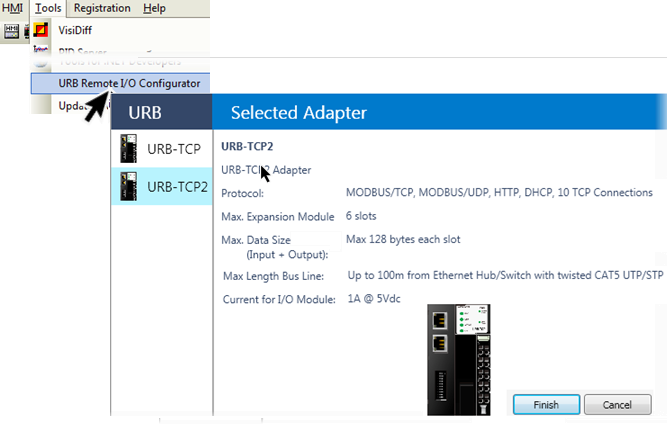
In order to enable data exchange between URB Remote I/Os and the controller, you use the utility URB Remote I/O Configurator to create .urli files that map between the I/Os and operand vectors within the controller. In this utility you:
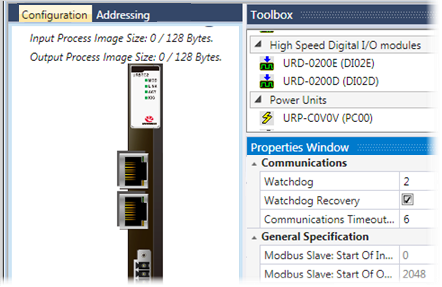
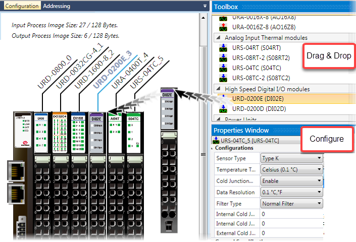
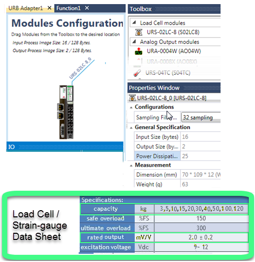
Configure your adapter and I/O modules
Set up addressing
Verify and Download the configuration and addressing to the adapter
Generate .urli files, these provide the I/O addressing map
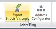
Export the .urli files from the Configurator
You can then import these files into VisiLogic. In your application, you:
Configure the Ethernetport to TCP/IP, initialize a TCP/IP socket, and configure MODBUS IP.
Use Vector Struct functions
to parse the I/O data exchange values between the I/O and your
controller and :
use the Import function on the Struct Function to import the .urli
files; this automatically inserts the correct addresses into the Struct
function.
The animated .gif below shows the process. Full instructions are given in the following sections.
|
|
|
|
NOTE: High-speed modules In order to configure properties of these modules, you must write the values to the adapter using the following values: Encoder4X = 0x0, Encoder2X = 0x1, Up = 0x2, Down = 0x3, UpClockAndInhibit = 0x4, UpClockAndReset = 0x5, DownClockAndInhibit = 0x6, DownClockAndReset = 0x7, UpClockAnDownClock = 0x8, ClockAndDirection = 0x9, FrequencyMeasurement1s = 0xC, FrequencyMeasurement100ms = 0xD, PulseWidthMeasurement = 0xE, PulseWidthAndPeriodMeasurement = 0xF |
|
URB Loadcell/Strain-gauge I/O Module
These I/O modules enable you to integrate a loadcell or strain-gauge in your control application.
A sample Loadcell application may be found in the VisiLogic Example applications.
To calculate the weight in user units you can use this formula ((A * 15.0 * C )/(D * B))*E.
Parameters A and B relate to the Unitronics I/O module's inputs.
Parameters C and D relate to the specifications of the Loadcell /Strain-gauge device you connect to the Unitronics' I/O module.
Parameter E, Scale Factor, can be used to fine tune measured results if required by using known weight, and according to calculated result, calculating the required offset percentage.
|
Refer to the Unitronics module's data sheet for details regarding calibration, zeroing, etc. |
After you have configured the modules, you set up addressing.
|
|
.
|
|
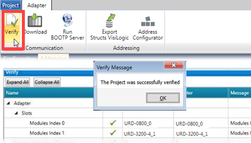
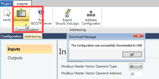
After you have configured the modules, and set up addressing, you verify the project, and then download the parameters to the adapter.
|
|
|
|
|
|
|
|
Note that you do not fill in any of the Struct parameters manually - all parameters are imported together with the .urli file.
Input files:
|
|
Output files:
|
|
The next image shows how the addresses you previously set in the Configurator are automatically matched with the imported files.

Communication with URB Remote I/O is via MODBUS TCP/IP, and requires you to:
Initialize the Ethernet card
Initialize a socket to TCP/IP
Configure MODBUS IP
For guidelines on building your application, please
refer to the Sample Applications for URB Remote I/O. These may be found
in the VisiLogic Examples folder, located at:
\Program Files (x86)\Unitronics\Unitronics VisiLogic_C\Examples\Version
900\Project examples\Communications\URB Remote IO\
Property |
Purpose |
IP Address |
Enter the IP of the Adapter |
Watchdog |
Check to enable the watchdog timer. If the adapter does not receive an answer from an I/O module within the defined Communication Timeout period, the watchdog activates. Timeout units: 1 unit=100msec Maximum units: 65535 |
Watchdog Recovery |
Select this enables the adapter to continue running after watchdog timeout and reset. |
Communications Timeout |
Units
of milliseconds 2-250. The
PLC sends a message 32 consecutive times, and waits for
an answer. At each Send, the PLC places
a value in the least significant bit of the struct tag
URB Remote I/O Adapter Communication Global > Timeout
Shift Register: 0 = Message Arrived /1 - Message
did not arrive before the timeout.
|
General Specification |
These are set during addressing and are read-only. |
The URB adapter IP defaults are:
Default IP: 192.168.100.100
Subnet mask: 255.255.255.0
Note that on the adapter, there is a sticker showing its MAC address.
There are two methods of changing the IP address:
· Via the URB Remote I/O Configurator's option, BOOTP Server.
· Via
DIP switch
These are physical switches on the adapter
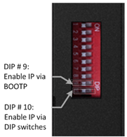
To enable the selected method, you must raise the appropriate DIP switch on the adapter. By factory default, the adapter is supplied with all switches down.
· Raise #9 to set IP via BOOTP Server:
-Enables the adapter BOOTP/DHCP
-The adapter sends 20 consecutive BOOTP/DHCP request messages every 2 seconds.
-If the BOOTP/DHCP server does not respond, the Adapter applies the latest
saved IP address
· Raise #10 to set IP via DIP switch:
You can then set the IP according to the description in the next table.
URB Adapter DIP Switches
# |
Role |
Description |
|
1 |
IP bit#0 |
Lowest IP Address octet when Switch #10=ON (raised) Example: XXX.XXX.XXX.IP |
|
2 |
IP bit#1 |
||
3 |
IP bit#2 |
||
4 |
IP bit#3 |
||
5 |
IP bit#4 |
||
6 |
IP bit#5 |
||
7 |
IP bit#6 |
||
8 |
IP bit#7 |
||
9 |
DHCP / BOOTP |
Enable DHCP / BOOTP |
|
10 |
Use DIP IP Value |
Enable IP Address set by DIP Switches |
Before you can set the IP address of the Remote IO adaptor via Unitronics BOOTP Server, you must raise DIP #9 (check that #10 is down)
1. Power OFF the URB adapter.
2. Raise DIP switch #9 to enable DHCP / BOOTP.
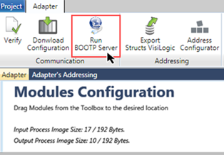
3. On the ribbon, click on Run BOOTP Server to open the utility.
5. Click Start BootP in the Unitronics BOOTP Server; the upper section displays Ethernet devices that are in the network.
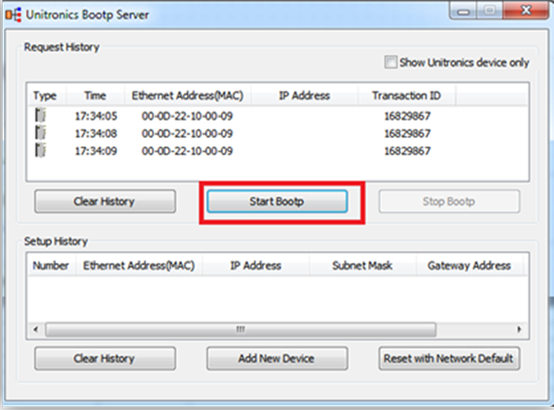
6. Power ON the URB adapter.
7. Locate the adapter’s MAC address and double-click on the row.
8. Enter the required IP address and select your PC Network card.
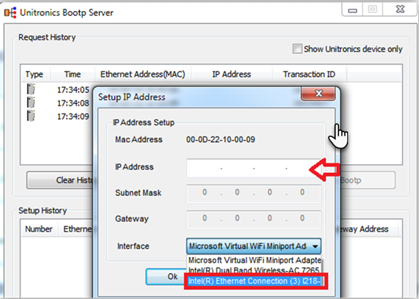
9. Click Ok. Now you should see the device in the bottom window including the IP address.

10. Power cycle the adapter; turn it off and on.
11. Use Ping from command line to check that the IP address is replying.
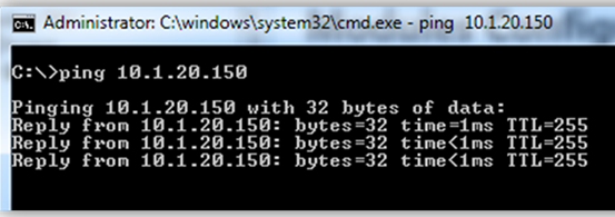
12. If the adapter replies successfully, then power off the adapter (URB-TCP) and lower DIP switch #9 (set to OFF).
13. Configure the adapter and IO modules and test.