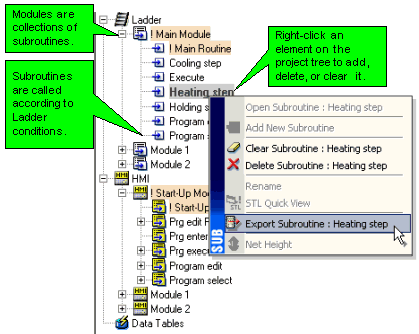
A module is a container of subroutines. Use modules and subroutines to divide your application into program blocks. You can then run these program blocks conditionally, from any point in your control application.

|
Note ♦ |
Within the program tree, elements are presented alphabetically. This does not affect the order in which the program runs. |
|
♦ |
Ladder Modules and subroutines can be moved via drag-and-drop, as can HMI Modules and Displays. Again, moving elements does not affect the order in which they run. The Main Ladder Module, Main Subroutine, Start-up HMI Module and the Start-up HMI Display cannot be moved via drag-and-drop or erased. For easy identification, they are always marked in orange. |
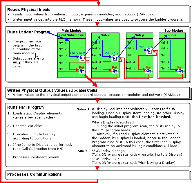
To control the Ladder program flow sequence and avoid loops, use the Call Subroutine function to conditionally call subroutines. Within a subroutine, you control the sequence by conditionally skipping over nets using Labels and Jump to Label functions. This enables you to shorten the program scan time.
A new VisiLogic project contains the main module and subroutine for the program. Each new subroutine contains a default number of nets and a Subroutine Return function.
Subroutines do not run if they are not called by Call Subroutine. If no Call Subroutine commands are included in the first subroutine of the main module, the program runs until it reaches the Subroutine Return function, and then jumps back to the beginning of the first subroutine.
|
Note ♦ |
If a subroutine does not run, the coils in that subroutine will not be updated. For example, Subroutine 4 contains |
|
♦ |
Some FBs require Configuration, such as SMS. The FB Configuration should be placed in the first subroutine of the main program module. If a Configuration is in a subroutine that is not called into the program, linked FBs will not be processed even if the activating condition for that FB has been turned ON. |
Subroutines can be reused as many times as required. Subroutines can also be exported and imported between projects.
A scan is a complete execution of the controller's entire program. The scan cycle is performed continuously.
|
Note ♦ |
Power-up tasks, relating to the status of SB2 Power-up bit, are performed when the controller is turned on. These tasks are performed before the program scan. |
|
♦ |
The scan time is stored in SI 0 Scan Time, Resolution: Units of 1 mSec. |
This checks to see that the scan execution does not exceed a certain period of time. If the program contains, for example, an endless loop, the Watchdog causes the PLC to enter Stop mode until the problem is fixed.
The Watchdog timer for all models is 1500msec.
