-
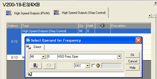
Click the Output line and select High Speed Outputs (Step Control).

-
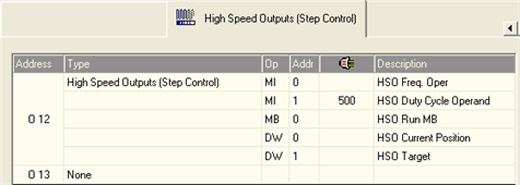
The Select Operand and Address dialog box appears five successive times, allowing you to link operands for Frequency, Duty Cycle, Run, Current Position, and Target Position.

If you are using a V570 with any model Snap-in I/O module, VisiLogic 7.00 or higher and the OS released with that version, you can use specific high-speed outputs to control stepper motors.
Note that any acceleration and deceleration that is needed to arrive at Target safely and accurately must be implemented in your Ladder application.
|
|
|
|
|
Parameter |
Type |
Function |
|
Frequency |
MI, ML, DW |
Note that F=1/T, where T is the duration time of a complete cycle. Frequency settings differ from npn to pnp output type.
Other frequency values are not supported. |
|
Duty Cycle |
MI, ML, DW |
The ratio of the "on" period of a cycle to the total cycle period. This value may be from 0-1000, and is expressed as a percentage. If, for example, the constant 750 is stored into the Duty Cycle operand, the duty cycle is equal to 75.0% This means that the pulse will hold a positive state during 75.0% of the total cycle. In the figure below, MI 22 Duty Cycle Value is equal to 250. This results in the duty cycle being 25% of the total cycle time.
If values out of range enter the Duty Cycle and Frequency operands, the output turns OFF and remains OFF until the values re-enter the range. |
|
Run |
MB |
Changes the operating mode of the output from normal output mode to HSO mode: 0 (SET)=Normal Mode, 1 (RESET): HSO Mode. |
|
Current Position |
DW |
This is the current location of the stepper. |
|
Target |
DW |
This is the location you want the stepper to move to. |
|
If your application requires acceleration/deceleration as is shown in the accompanying figure, you can control the speed of movement via the Ladder application. To see how, check the sample application Stepper Control. |
|