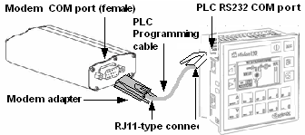
The following figure shows you how to connect a controller to a modem.

|
Note ♦ |
The programming cable is a 4-wire cable. The cable is included with the Vision all-in-one kits. |
Unitronics' modem kits
Use with a Unitronics PLC programming cable, as shown in the figure above. Kits contain a modem that is compatible with Unitronics controllers and related hardware. The Products section of the Unitronics web site contains kit descriptions and specifications.
Other modems
-Use a Unitronics PLC programming cable to connect the PLC to a modem adapter. You can order modem adapters from Unitronics.
-Construct your own D-type to D-type connector cable to connect the programming cable to the modem's serial port, according to the pin-outs provided below.
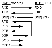
The next figure shows the interface between the Data Communications Equipment (DCE; the modem) and the Data Terminal Equipment (DTE; the controller or PC). The arrows show the direction of data flow. Note that:
Transmitted data (TXD) is input to the modem, output from the PLC
Received data (RXD) is input to the PLC, but output from the modem

|
Note ♦ |
Unitronics controllers do not support all the control lines. |
|
♦ |
Modems should be initialized via the Modem Services> Prepare Modem procedure. This procedure:
|
|
♦ |
Connecting DSR and RTS signals causes the modem to be always ready to transmit\receive data. |
Unitronics' kits contain all of the elements you need to connect a controller to a modem using the appropriate PLC programming cable, as shown in the first figures at the beginning of this section.
|
Note that you must remove the PC adapter from the PLC programming cable and replace it with the modem adapter supplied in the kit. |
|
In order to work with Unitronics controllers, you must initialize the modem via the procedure detailed in the Prepare PLC Modem topic.
The following list shows modem adapters supplied with the kits and their pin-outs. For updated information, consult your Unitronics distributor.
Standard Landline and Siemens GSM/GPRS modems
Sony Ericsson GM29 and Enfora GSM/GPRS modems
|
Note ♦ |
Wavecom modem kits do not contain the PC to modem cable, MJ10-22-CS32, that is required for the Wavecom Prepare Modem procedure. This cable is available by separate order. |
If you are using a modem from an independent source, you can order one of the modem adapters described in the preceding section from Unitronics, and use this adapter to connect your modem to the PLC via the PLC programming cable.
You can construct a D-type modem adapter yourself, using the appropriate pin-outs shown in the preceding section.
You can also construct a cable with 2 male D-type connectors, and then use it to connect a modem's serial port directly to the PC adapter on the PLC programming cable as shown in the next figure.

The tables below give the pin-outs of the programming cables, and show you an example of the pin connection you can use to construct a cable with 2 male D-type connectors to connect a PLC to a standard landline modem.
Vision 4-wire Programming Cable
|
PC -side Adapter MJ10-22-CS25 |
|
PLC-side Programming port |
||||
|
PC signals |
D-Type 9 pin, female |
RJ11 |
|
RJ11 |
Controller signals |
|
|
DTR (out) |
4 |
1 |
|
6 |
DSR (in) |
Unused |
|
GND |
5 |
2 |
|
5 |
GND |
|
|
TXD (out) |
3 |
3 |
|
4 |
RXD (in) |
|
|
RXD (in) |
2 |
4 |
|
3 |
TXD (out) |
|
|
GND |
5 |
5 |
|
2 |
GND |
|
|
DSR (in) |
6 |
6 |
|
1 |
DTR (out) |
Unused |
|
Note ♦ |
The 4-wire programming cable supplied with the controller connects RJ11 pins 2,3,4,5 to pins 5,4,3,2 respectively. |
Example: D-type modem adapter cable to connect a Vision controller to a standard landline modem
|
Modem-side |
|
PLC-side (D-type 9-pin, male) |
||
|
DSR (out) + RTS (in) |
6+7 |
|
|
|
|
GND |
5 |
|
5 |
GND |
|
RXD (out) |
2 |
|
3 |
RXD (in) |
|
TXD (in) |
3 |
|
2 |
TXD (out) |
|
GND |
5 |
|
5 |
GND |