You can use a standard Windows application called Hyperterminal to perform certain tasks, such as changing a modem’s communication rate.
|
Note ♦ |
The modem driver does not need to be installed in order to access the modem via Hyperterminal. |
The Unitronics’ cable provided with modem kits does not provide a standard connection. This connection is adapted to support the fact that Unitronics controllers do not support the control lines. The cable shorts the DSR and the DTR together, which ensures that the terminal is always ready to receive data.
For more information, refer to the topic Modem Connection and Pinouts.
Generally, when you transmit data, you send it out. Note, however, that transmitted data (TXD) is input to the DCE. A Receive Data signal (RXD) is input to the DTE, but output from the DCE.
Therefore, the RXD and TXD signals are crossed within the majority of modems. This means that a straight through "one to one" cable is generally all that is necessary between a modem and a controller or PC serial port.
|
RXD Receive Data |
Input for DTE devices (Receive), output for DCE devices. This is the data channel from the DCE device to the DTE device. |
|
TXD Transmit Data |
Output for DTE devices (Send), input for DCE devices. This is the data channel from the DTE device to the DCE device. |
|
GND Signal Ground |
Signal return for all signal lines. |
|
RTS Request To Send |
Terminal is ready to receive data. When the DTE is ready to receive data, the DTE serial port RTS signal is ON. |
|
CTS Clear To Send |
Terminal is ready --not related to data transfer. |
|
DTR Data Terminal Read |
It is an output for DTE devices and an input for DCE devices. This signal is typically used in UNIX to show that the port has been activated or "opened". |
|
DSR Data Set Ready |
Detects if the RS232 is actually connected. |
|
DCD Data Carrier Detect |
Turns ON when the modems connect. |
|
RING |
Turns ON when someone is calling the DTE. |
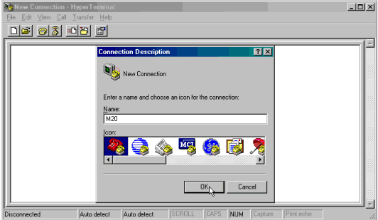
Open Hyperterminal. The program can generally be located by clicking the Start button in the lower left corner of your screen, then selecting Programs>Accessories>Communications>Hyperterminal. The New Connection window opens as shown below.
Note ♦ Hyperterminal generally starts by pointing to the internal modem, if one is installed on the PC.

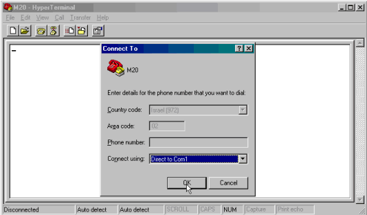
Enter a name for the new connection and select an icon, and then click OK. The Connect To box opens .
Select a COM port for the modem, and then click OK.

The Port Settings box opens as shown below. To enable your PC to communicate with the modem, set the COM port parameters to a BPS of either 9600 or 19200, Data bits=8, Parity=N, Stop bits=1, Flow control=None, and then click OK.

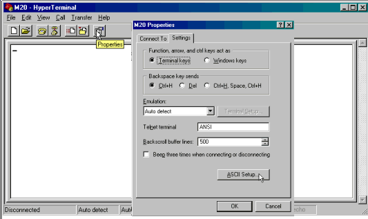
Open the modem’s Properties box by clicking on the Properties button, then open ASCII Setup.

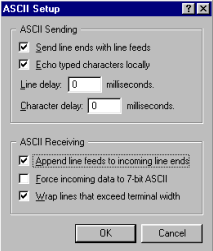
Select the options shown below, and then click OK.

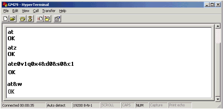
Hyperterminal is now connected to your PC via COM 1; the ASCII settings now enable you to enter commands via the PC keyboard and see the replies from the modem within the Hyperterminal window.
To test the connection, type AT; if the connection is valid the modem will respond 'OK'.
Typical initialization strings used with a Siemens M20-type modem are shown below.

Note ♦ The modem must reply with either OK or READY to each command entered. If the modem fails to answer, the command has not been processed.
|
+++ |
Escape Sequence. This causes the modem to close connections and go back to command mode |
|
AT |
This command means Attention; and is used to begin a session |
|
AT&F |
Restores factory default settings |
|
ATZ |
Resets the modem. This command may take time to implement, so the response from the modem may be delayed |
|
ATE0 |
No Echo |
|
V1 |
Enable Verbose (long) response |
|
Q0 |
Respond |
|
X4 |
Detailed answers |
|
&D0 |
Ignore DTR |
|
&S0 |
DSR always ON. |
|
&S1 |
DSR OFF in command and test modes |
|
&C1 |
Give the user a signal for the DCD |
|
ATS0=1 |
Auto-Answer after 1 ring |
|
&W |
Burn the configuration into the modem’s non-volatile memory |
Once the modem is successfully initialized, you can use Hyperterminal to initialize the modem to SMS mode.
|
Command |
Description |
Notes |
|
at+cpin=? |
Is a pin number required? |
|
|
at+pin=” xxxx” xxxx |
Is the pin number set in the application? |
|
|
at+creg? |
Has the SIM card been registered with the local cellular provider? |
Should return one of two answers:
|
|
at+cmgf=1 |
Go to text mode |
|

|
Notes ♦ |
Commands including question marks are run for verification twice. If the command is not verified during the second attempt, the attempts stop. |
|
♦ |
If the SIM requests the PUK number, the SIM must be taken out of the modem and installed into a phone to enable the number to be entered. |
|
♦ |
If the SIM is full, the SIM must be taken out of the modem and installed into a phone to enable the SIM to be cleared. |
|
♦ |
The modem must be able to support Text mode. P.D.U. mode is not supported. |
It uses the Send command, containing the number to be called: AT+CMGS= ”phone number”.
The controller then waits for the reply '>'.
When the '>' is received, the controller sends the message, ending the line with CTRL_Z
If the message is successfully sent, the controller will receive a message of confirmation,+CMGS:xx. When this message is received by the controller, SB 184 turns ON. The confirmation message is acknowledged by OK.
If :
the message of confirmation is not received within 15 seconds, or
the '>' is not received within 3 seconds, SB 185 turns ON.
When the controller receives an SMS text message:
It receives the command: +CMTI: “SM” ,xx. Xx is a number in the controller's memory, 1 to 20.
When the message is received, the controller asks the modem for the text via the command AT+CMGR=xx
The modem replies with +CMGR, including the phone number, status, text, and concluding with OK.
|
Note ♦ |
When a COM port has been successfully initialized, the relevant bit turns ON: SB 80 , 82, 83 or 84. |
The instructions below show you how to construct a communications 'Sniffer'. This device enables you to use Hyperterminal to view communication strings flowing between a PLC and an external, connected device such as a bar code reader.
|
‘Sniffer’ is connected to the external device. |
|
‘COM’ is connected to the PLC. |
|
The completed Sniffer is connected to a PLC communication port, PC and external device.
Note that communication cables are the programming cable provided by Unitronics.
|
|
To make a Sniffer, you need:
An adapter.
Two 1N4148 or 1N914 diodes.
|
|
|
|
|
|
|
|
|
|
|
|
|
|
Note ♦ |
In order to run view the strings in Hyperterminal, you must set the program to display ASCII strings as described above in Using Hyperterminal. |