Notes
-
Each module contains a 32-bit IO - Status tag. A value of 0x00 = No Errors.
If the error message is to Contact Support, supply the specific error code to the support team.
Note that LED indications are provided below. -
The file Connected_IOs_Module_Data.csv. is created by the controller at powerup and placed on the root of the SD card. The file contains data regarding any Uni-I/O modules connected to the controller. The data includes the position relative to the controller, model, serial number, and operating system version numbers of the of the Uni-I/O module
-
IO Bus Error screenIO Bus Error screen
At powerup and HMI reset, if the system detects IO bus errors, the following screen will be displayed showing the error code.
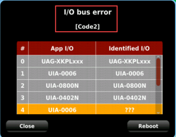
Codes
0 - OK
1 - Connectivity / Wiring problems
2 - IO configuration mismatch – type mismatch: the UniLogic Hardware Configuration contains an IO module of a model different from the modules actually connected to the controller
3 - IO configuration mismatch – number mismatch: for example the UniLogic Hardware Configuration contains 2 IOs, but 3 are actually physically connected.
4 - Unitronics – IO exists, but returns an unexpected answer during IO initialization.
5 - A specific IO is faulty, check the IO after the last I/O listed in the table.