EtherCAT: Third-Party Devices
UniStream controller models that can support a Unitronics EtherCAT master module can exchange data with third-party EtherCAT slave devices.
A single UniStream can support a total of 32 EtherCAT nodes. This includes any EtherCAT Servo drives, and EtherCAT Remote URB adapters, as well as third-party EtherCAT devices.
You can exchange data via SDO requests and PDOs, via the slave's I/O struct.
Definition Files: Slaves Library
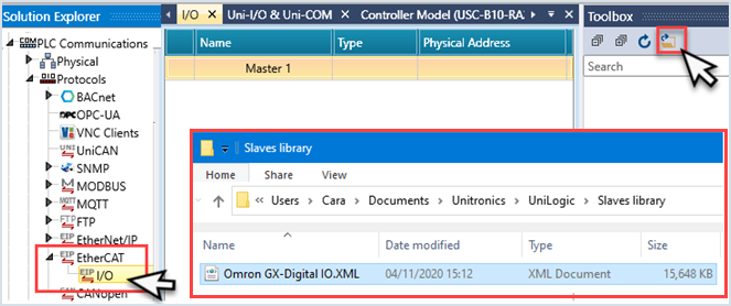
UniLogic imports the EtherCAT definition files from the Slaves Library.
To populate the library:
-
In the Solution Explorer, select PLC Communications > Protocols> EtherCAT> I/O.
-
Click the Open Slave Library icon to open the library location; place your Slave definition files here.
-
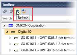
Click the Refresh icon to view the files in the Toolbox.
Using Third-party devices in your application
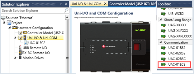
To begin, include an EtherCAT Master Module in your application:
-
In the Solution Explorer, select Hardware Configuration>Uni-I/O and Uni-COM, and add an EtherCAT Master module.
-
Drag & drop or double-click your devices to include them in your project.
Note that UniLogic adds a struct for each device.
Click a slave device you have added in order to see its Properties; you can click to edit PDO mapping, and view its SDO Mapping.

-
Use the EtherCAT SDO functions described below to communicate data.
When you include an SDO FB in your project you assign a tag for the struct name.
The parameters in these structs are read-only.
 |
SDO FBs
|
EtherCAT Write SDO

|
|
|
|
|
A
|
EtherCAT I/O Struct
|
Select the device you are using
|
|
B
|
Execute
|
Rising Edge Triggers FB
|
|
C
|
SDO Index
|
Contains the Index to write to
|
|
D
|
SDO sub-index
|
Contains the Sub-Index to write to
|
|
E
|
Number of bytes to write
|
Bytes to write
|
|
F
|
Value to Write
|
Contains the value to write
|
|
G
|
Status
|
0 = Success
1 = in_progress
-1 = internal error
-4 = not connected
-5 = value overflow ( can write up to 4 bytes)
-11 = null_pointer
-12 = out_of_memory
-13 = invalid_service_ref
-14 = service_without_sdo
-15 = resolve_ident
-16 = data
-17 = invalid_size
|
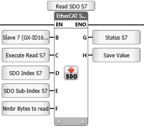
EtherCAT SDO Read
|
|
|
|
|
A
|
EtherCAT I/O Struct
|
Select the device you are using
|
|
B
|
Execute
|
Rising Edge Triggers FB
|
|
C
|
SDO Index
|
Contains the Index to read from
|
|
D
|
SDO sub-index
|
Contains the Sub-Index to read from
|
|
E
|
Number of bytes to Read
|
Number of bytes to copy
|
|
F
|
Status
|
0 = Success
1 = in_progress
-1 = internal error
-2 = queue full (too many read requests)
-11 = null_pointer
-12 = out_of_memory
-13 = invalid_service_ref
-14 = service_without_sdo
-15 = resolve_ident
-16 = data
-17 = invalid_size
|
|
G
|
Value to read
|
Function will store the value here
|
EtherCAT Master Module Struct
This is a system struct.
|
Parameter Name |
Data Type |
|
|
USB Flash Inserted |
BIT |
Is ON when there is a DOK
in the modules USB port |
|
Module Connected |
BIT |
Turns ON when the module
is physically connected to CPU |
|
Module Ready |
BIT |
Startup complete, Module
is ready to start communication with the CPU |
|
Module Type |
UINT8 |
Value indicates Module
type:
0 = UAC-02EC2 |
|
Initialization Status |
UINT32 |
Status indications:
0
= Not initialized
3 = Topology Mismatch: the order of the EtherCAT
elements in the project' Hardware Configurations does not match
the order in which they are physically connected to the controller
5
= Initialized
successfully
Other codes= Internal |
|
Current Firmware Version |
STRING-ASCII |
Indicates the firmware
version currently installed in the module. |
|
Inserted Image Version |
STRING-ASCII |
Indicates
the firmware version on the connected DOK |
|
Average cycles between
diagnostics packages |
UINT32 |
Statistics |
|
Average time between
diagnostics packages |
UINT32 |
Statistics |
|
PI Send Errors Count |
UINT32 |
Statistics
|
|
PI Receive Errors Count |
UINT32 |
Statistics |
|
Wrong Working Counter
Frames |
UINT32 |
Statistics |
|
Slave Response Time; |
UINT32 |
Statistics |
|
Light all LEDs up |
BIT |
Internal |
|
Average Cycle Time |
UINT32 |
Internal |
|
Min Cycle Time |
UINT32 |
Internal |
|
Max Cycle Time |
UINT32 |
Internal |
|
Communication Active |
BIT |
ON when communication between
CPU and module is ok |
|
Diagnostics Mode |
BIT |
ON
when module is in motion diagnostics mode |
|
Reserved |
UINT32f0...821 |
|
|
Master Bus OK |
BIT |
ON when Bus is OK |
|
Mandatory> slave is in wrong state |
BIT |
|
|
Mandatory slave is offline |
BIT |
|
|
Hot-connect slave is in wrong state |
BIT |
|
|
Hot-connect slave is offline |
BIT |
|
|
ViolationTimeCntr |
UINT32 |
Internal |
|
EtherCat master state |
UINT32 |
Internal |