Certain I/O modules, such as UID-0808T offer an Advanced Functions option which enables complex I/O functions, including counters and built-in Scenarios.
To use Advanced Functions:
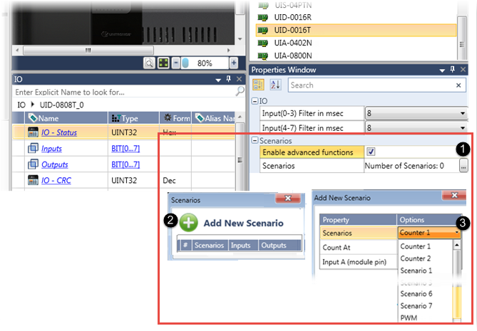
In the Properties Window, check Enable Advanced Functions and click Number of Scenarios.
Click Add New Scenario.
Under Scenarios, click the drop-down arrow and select the desired option.
A Scenario is a pre-configured implementation of specific functions. A Scenario displays an illustration that shows the exact functions it will carry out, and the I/Os that the functions will use.
Note that when you add a counter or scenario, UniLogic adds fields to the I/O struct that enables you to implement the added functionality in your project.

The Counter Value increments or decrements when an input changes state. You select which state change to count.

Options
|
Property Name |
Options |
|
Count At |
|
|
Input A |
Select the input to count |
Counter 1 Struct
|
Parameter Name |
Type |
Description |
|
CT1: Counter Direction |
Bit |
Determines the counter direction: 0=Increment(default), 1=Decrement Read/Write |
|
CT1: Counter Value |
UINT32 |
Contains the current Counter Value |
|
CT1: Reset Counter |
Bit |
Set this bit in your program to load the Preset Value to the Counter Value. In order to initialize the counter, use a counter Preset Value of 0. Reset by user. |
|
CT1: Preset Value |
UINT32 |
When Reset Counter bit = 1, this tag value is written to Counter Value. Default value = 0 |
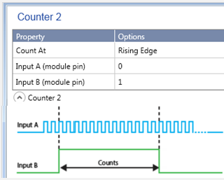
The Counter Value increments or decrements when an input changes state. You set the state change that is counted.
However, the counter is conditional: the state change of Input A is counted only when Input B is set.
Options
|
Property Name |
Options |
|
Count At |
|
|
Input A |
Select the input to count |
|
Input B |
Select the input that controls the counter |
Counter 2 Struct
|
Parameter Name |
Type |
Description |
|
CT2 Counter |
UINT32 |
Current Counter Value |
|
CT2: Counter Direction |
Bit |
Determines the counter direction: 0=Increment(default), 1=Decrement Read/Write |
|
CT2: Reset Counter |
Bit |
Set this bit in your program to load the Preset Value to the Counter Value. In order to initialize the counter, use a counter Preset Value of 0. Reset by user. |
|
CT2: Preset Value |
UINT32 |
When Reset Counter bit = 1, this tag value is written to Counter Value. Default value = 0 |
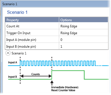
A Scenario displays an illustration that shows the exact functions it will carry out. You select the I/Os that the functions will use.
In this scenario:
if the struct parameter Enable Immediate (Hardware) is set,
when the Counter Value reaches the Preset Value,
the module immediately forces the Preset Value to the hardware counter, immediately resetting the hardware counter.
To initialize the counter, use Preset Value = 0 (default).
Options
|
Property Name |
Options |
|
Count At |
Rising Edge Falling Edge Rising Edge + Falling Edge |
|
Trigger On Input |
Set the state change that activates the scenario
|
|
Input A |
Select the input to count |
|
Input B |
Select the input that resets the counter |
Struct
|
Parameter Name |
Type |
Description |
|
SC1: Reset Counter |
Bit |
Set this bit in your program to load the Preset Value to the Counter Value. In order to initialize the counter, use a counter Preset Value of 0. Reset by user. |
|
SC1: Preset Value |
UINT32 |
When Reset Counter bit = 1, this tag value is written to Counter Value. Default value = 0 |
|
SC1: Counter Value |
UINT32 |
Current Counter Value |
|
SC1: Enable Immediate (Hardware) |
Bit |
If Enable Immediate = 1, when Input B changes state, the Preset Value is immediately forced to the hardware counter. This is independent of the program scan. |
|
SC1: Counter Direction |
Bit |
Determines the counter direction: 0=Increment(default), 1=Decrement Read/Write |
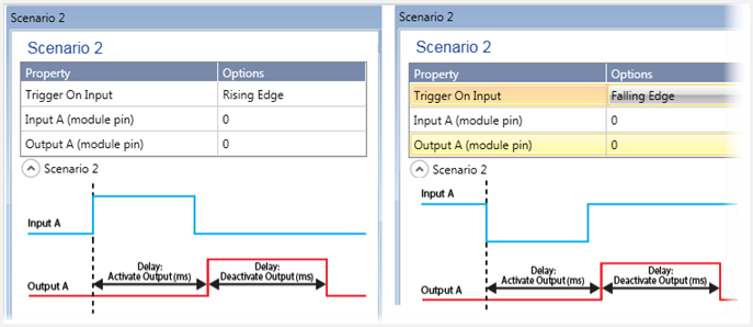
The state change of Input A triggers the scenario. You use the system struct to:
Set a time delay to activate the output.
Set a time delay to deactivate the output.
The struct tag Output Action Logic determines whether the Output will turn ON (Set) or OFF (Reset): 0 =Set, 1=Reset.
Options
|
Property Name |
Options |
|
Trigger On Input |
Select the state change that activates the scenario
|
|
Input A |
Select the Scenario trigger |
|
Output A |
Select the output to control |
|
Parameter Name |
Type |
Description |
|
SC2: Started Scenario |
Bit |
Scenario started. Bit=1 while Scenario is running |
|
SC2: Ended |
Bit |
Scenario ended |
|
SC2: Reset Scenario |
Bit |
Stops Scenario, resets the Started Scenario bit, and toggles Output A |
|
SC2: Delay Activate Output |
UINT32 |
Delay (ms) from input trigger to output activation |
|
SC2: Delay Deactivate Output |
UINT32 |
Time duration ( ms) to keep the output action active |
|
SC2: Output Action Logic |
UINT8 |
Select the type of Output action: 0 =Set, 1=Reset |
|
SC2: Enable Scenario |
Bit |
Enable/disable scenario. If this is OFF, Scenario cannot run. |
This scenario is triggered by a counter value. The scenario counts the pulses of Input A. When the Counter Value is reached (Counter Match), the scenario triggers. Via the scenario struct you can:
Set a time delay to activate the output.
Set a time delay to deactivate the output.
You can also use the scenario trigger to immediately write the Preset Value to the Counter Value, immediately resetting the hardware counter.
The struct tag Output Action Logic determines whether the Output will turn ON or OFF: 0 =Set, 1=Reset.

Options
|
Property Name |
Options |
|
Count At |
|
|
Input A |
Select the input to count |
|
Output A |
Select the output to control |
Scenario 3 Struct
|
Parameter Name |
Type |
Description |
|
SC3: Started Scenario |
Bit |
Scenario started. Bit=1 while Scenario is running |
|
SC3: Ended |
Bit |
Scenario ended |
|
SC3: Reset Scenario |
Bit |
Stops Scenario, resets the Started Scenario bit, and toggles Output A |
|
SC3: Reset Counter |
Bit |
Set this bit in your program to load the Preset Value to the Counter Value. In order to initialize the counter, use a counter Preset Value of 0. Reset by user. |
|
SC3: Counter Value |
UINT32 |
Current Counter Value |
|
SC3: Counter Match Value |
UINT32 |
This is the counter value that triggers the Scenario (number of pulses of Input A) |
|
SC3: Delay Activate Output |
UINT32 |
Delay (ms) from input trigger to output activation |
|
SC3: Delay Deactivate Output |
UINT32 |
Delay (ms) before the output is deactivated (duration of output) |
|
SC3: Output Action Logic |
UINT8 |
Select the type of Output action: 0 =Set, 1=Reset |
|
SC3: Preset Value |
UINT32 |
When Reset Counter bit = 1, this tag value is written to Counter Value. Default value = 0 |
|
SC3: Enable Immediate (Hardware) |
Bit |
If Enable Immediate = 1, when Counter Value = Counter Match, the Preset Value is immediately forced to the hardware counter. This is independent of the program scan. |
|
SC3: Counter Direction |
Bit |
Determines the counter direction: 0=Increment(default), 1=Decrement Read/Write |
|
SC3: Enable |
Bit |
Enable/disable scenario. If bit = 0, Scenario cannot run. |
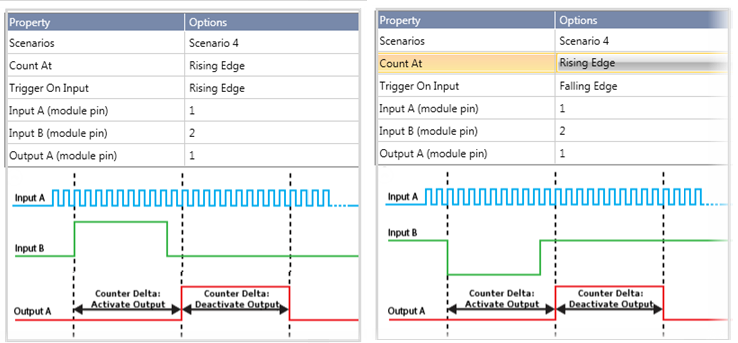
This scenario is triggered by a counter value. The scenario counts the pulses of Input A. When the Counter Value is reached, the scenario triggers. Via the scenario struct you can:
Set a delay (number of pulses) to activate the output.
Set a delay (number of pulses) to deactivate the output.
The struct tag Output Action Logic determines whether the Output will turn ON or OFF: 0 =Set, 1=Reset.
Options
|
Property Name |
Options |
|
Count At |
|
|
Trigger On Input |
Select the state change that activates the scenario:
|
|
Input A |
Select the input to count |
|
Input B |
Select the Scenario trigger |
|
Output A |
Select the output to control |
Scenario 4 Struct
|
Parameter Name |
Type |
Description |
|
SC4: Started Scenario |
Bit |
Scenario started. Bit=1 while Scenario is running |
|
SC4: Ended |
Bit |
Scenario ended |
|
SC4: Reset Scenario |
Bit |
Stops Scenario, resets the Started Scenario bit, and toggles Output A |
|
SC4: Reset Counter |
Bit |
Set this bit in your program to load the Preset Value to the Counter Value. In order to initialize the counter, use a counter Preset Value of 0. Reset by user. |
|
SC4: Counter Value |
UINT32 |
Current Counter Value |
|
SC4: Counter Delta: Activate Output |
UINT32 |
Delay (number of pulses to count) from input trigger, to output activation |
|
SC4: Counter Delta: Deactivate Output |
UINT32 |
Delay (number of pulses to count) before the output is deactivated (duration of output) |
|
SC4: Output Action Logic |
UINT8 |
Set the type of Output action: 0 =Set, 1=Reset |
|
SC4: Preset Value |
UINT32 |
When Reset Counter bit = 1, this tag value is loaded to Counter Value. Default value = 0 |
|
SC4: Counter Direction |
Bit |
Determines the counter direction: 0=Increment(default), 1=Decrement Read/Write |
|
SC4: Enable Scenario |
Bit |
Enable/disable scenario. If this is OFF, Scenario cannot run. |
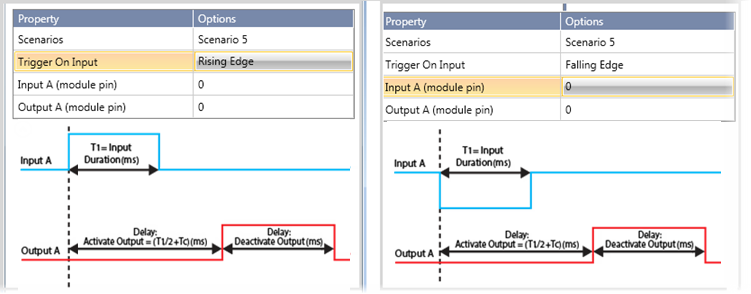
Use this scenario to control an output via a calculation based on Input duration (time-based).
The hardware tracks the duration of Input A (T1). The scenario calculates the delay, ((T1÷ 2) + Tc), and activates Output A. Via the Scenario struct, you set a time delay to deactivate Output A.
The struct tag Output Action Logic determines whether the Output will turn ON or OFF: 0 =Set, 1=Reset.
In the Scenario images below:
T1 = Duration of Input A
Tc = a constant value in mS, set by the user via the Scenario struct
Delay to Activate Output A = (T1÷ 2) + Tc
Options
|
Property Name |
Options |
|
Trigger On Input |
Select the state change that activates the scenario:
|
|
Input A |
Select the Scenario trigger |
|
Output A |
Select the output to control |
Scenario 5 Struct
|
Parameter Name |
Type |
Description |
|
SC5: Tc (Constant set by user, ms) |
UINT32 |
This is the constant value (ms) used to calculate Delay: Activate Output |
|
SC5: Started |
Bit |
Scenario started. Bit=1 while Scenario is running |
|
SC5: T1, Input Duration (read-only) |
UINT32 |
The amount of time Input A is active, measured by the hardware. |
|
SC5: Ended |
Bit |
Scenario ended |
|
SC5: Reset Scenario |
Bit |
Stops Scenario, resets the Started Scenario bit, and toggles Output A |
|
SC5: Delay Deactivate Output |
UINT32 |
Delay (in ms) before the output is deactivated (duration of output) |
|
SC5: Output Action Logic |
UINT8 |
Select the type of Output action: 0 =Set, 1=Reset |
|
SC5: Enable Scenario |
Bit |
Enable/disable scenario. If this is OFF, Scenario cannot run |
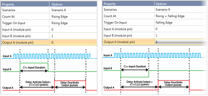
Use this scenario to control an output via a calculation based on Input duration (pulse-based).
While Input B is ON, the hardware counts the pulses of Input A (C1). The scenario calculates the delay, ((C1÷ 2) + Cc), and activates Output A. Via the Scenario struct, you set the number of pulses to be counted before deactivating Output A.
The struct tag Output Action Logic determines whether the Output will turn ON or OFF: 0 =Set, 1=Reset.
In the Scenario images below:
C1 = Duration of Input A (pulses count)
Cc = a constant value (a number of pulses), set by the user via the Scenario struct
Delay to Activate Output A = (C1÷ 2) + Cc
Options
|
Property Name |
Options |
|
Count At |
|
|
Trigger on Input |
Select the state change that activates the scenario:
|
|
Input A |
Select the input to count |
|
Input B |
Select the Scenario trigger |
|
Output A |
Select the output to control |
Scenario 6 Struct
|
Parameter Name |
Type |
Description |
|
SC6: Started |
Bit |
Scenario started. Bit=1 while Scenario is running |
|
SC6: Ended |
Bit |
Scenario ended |
|
SC6: Reset Scenario |
Bit |
Stops Scenario, resets the Started Scenario bit, and toggles Output A |
|
SC6: C1, Input Duration (read-only) |
UINT32 |
The number of pulses Input A is on, counted by the hardware. |
|
SC6: Cc (Constant, set by user, pulses) |
UINT32 |
This is the constant value (pulses to count) used to calculate Delay:Activate Output. |
|
SC6: Delay: Deactivate Output |
UINT32 |
Delay (number of pulses to count) before the output is deactivated (duration of output) |
|
SC6: Output Action Logic |
UINT8 |
Select the type of Output action: 0 =Set, 1=Reset |
|
SC6: Enable Scenario |
Bit |
Enable/disable scenario. If this is OFF, Scenario cannot run. |
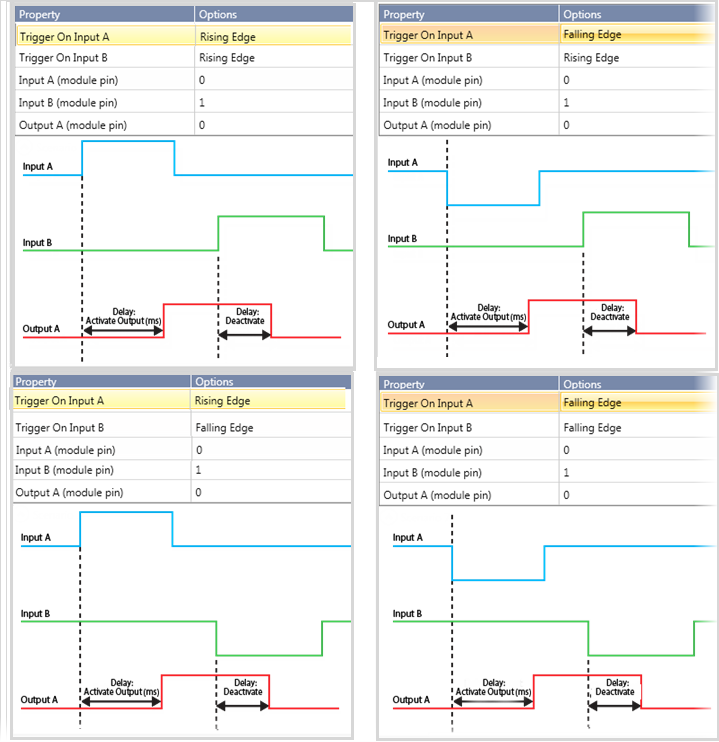
This scenario uses two inputs, Input A to both trigger the scenario and the delay timer that activates Output A, and Input B to trigger the delay timer that deactivates Output B. Use the scenario struct to
Set a time delay to activate the output.
Set a time delay to deactivate the output.
The struct tag Output Action Logic determines whether the Output will turn ON or OFF: 0 =Set, 1=Reset.
Options
|
Property Name |
Options |
|
Trigger on Input A |
Select the state change that activates both the scenario and the delay timer that activates the output:
|
|
Trigger on Input B |
Select the state change for Input B that activates the delay timer that deactivates the output:
|
|
Input A |
Select the input that: |
|
Input B |
Select the input to activate the timer for Delay: Deactivate Output |
|
Output A |
Select the output to control |
Scenario 7 Struct
|
Parameter Name |
Type |
Description |
|
SC7: Started Scenario |
Bit |
Scenario started. Bit=1 while Scenario is running |
|
SC7: Ended |
Bit |
Scenario ended |
|
SC7: Reset Scenario |
Bit |
Stops Scenario, resets the Started Scenario bit, and toggles Output A |
|
SC7: Delay Activate Output |
UINT32 |
Delay ( in ms) from input trigger to output activation |
|
SC7: Delay Deactivate Output |
UINT32 |
Time duration ( in ms) to keep the output action active |
|
SC7: Output Action Logic |
UINT8 |
Select the type of Output action: 0 =Set, 1=Reset |
|
SC7: Enable Scenario |
Bit |
Enable/disable scenario. If this is OFF, Scenario cannot run. |
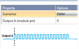
Use this to implement PWM on of the module's outputs.
Options
|
Property Name |
Options |
|
Output A (module pin) |
Select the PWM output |
PWM Struct
|
Parameter Name |
Type |
Description |
|
PWM1: Enable |
Bit |
Enable/disable scenario |
|
PWM1: Frequency |
UINT8 |
PWM Frequency, Range 1 -10 Hz (default 0) |
|
PWM1: PWM Duty Cycle |
UINT8 |
PWM Duty Cycle (1%) Range 0 -100 (default 0 ) |
|
PWM1: Parameter Error |
Bit |
Duty Cycle> 100% Frequency=0 or >10 Turns on only if PWM Enable =1, and if Frequency and/or Duty Cycle are out of range. |
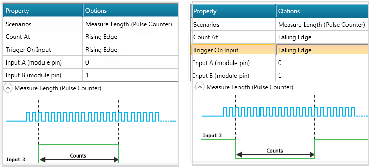
This scenario enables you to count pulses in order to measure the length of an object on a moving conveyor belt.
Options
|
Property Name |
Options |
|
Scenarios |
Measure Length (Pulse Counter) |
|
Count At |
Rising Edge Falling Edge |
|
Trigger on Input |
Rise Fall |
|
Input A |
Select the physical pin |
|
Input B |
Select the physical pin |
Scenario Struct
|
Parameter Name |
Data Type |
Description |
|
IO Status |
UINT32 |
|
|
Inputs |
Bit Array 0-7 |
Value of inputs (0 or1) |
|
Counter Value |
UINT32 |
Current counter Value |
|
Counter Direction |
Bit |
Set direction of counter: (0=Down, 1=Up) |
|
Occurrences Counter |
UINT32 |
Number of times Scenario has run |
|
Last Measurement |
UINT32 |
Last Measurement Value |
|
Start Scenario |
Bit |
On while Scenario is running |
|
Scenario Ended |
Bit |
Scenario ended |
|
Preset Value |
|
When Reset Counter Bit=1, Preset Value is loaded to counter value. Default=0 |
|
Outputs |
Bit Array 0-7 |
Value of outputs (0 or1) |
|
Reset Counter |
Bit |
Reset Counter: 0 = Do not Reset 1= Reset |
|
Enable Scenario |
Bit |
Enable/disable scenario (I/O becomes general purpose when scenario is disabled) |